Link zur deutschen Version: Experimentelle und analytische Untersuchung der Tragfähigkeit von 3D-gedrucktem Beton
In recent years, 3D printed concrete (3DPC) has primarily been used for non-structural applications, such as formworks for complex geometries or hybrid components, rather than as a load-bearing material. The primary limitation arises from the lack of well-established mechanical models and a structural design basis, caused by uncertainties related to the layered nature of 3DPC and the challenges of reinforcement integration. In fact, due to the layered structure caused by the printing process, 3DPC exhibits anisotropic behaviour: the strength and failure modes thus depend not only on the concrete matrix but also on the quality of the bond between adjacent layers. Consequently, design rules developed for conventional concrete cannot always be directly applied to 3DPC. To enable the structural use of 3DPC, it is therefore essential to develop reliable testing methods and failure criteria, which is a fundamental step towards defining the load-bearing capacity of printed concrete and establishing a consistent design framework. To better understand how 3DPC performs under different loading conditions, we present in the following two test methodologies developed at ETH Zürich: the modified slant shear test and the direct tensile test on reinforced 3D printed concrete ties.
Modified Slant Shear Test
The first type of test presented is a modification of the slant shear test, which is commonly used for conventional concrete to study the interfacial bond strength between concrete cast at different times, or concrete and a repair material (e.g., adhesives). In this test, according to EN 12615:1999, a prism with an interface plane inclined at an angle of  = 60° to the horizontal is loaded under uniaxial compression to assess the shear transfer capacity along that interface.
In the context of 3DPC, the Modified Slant Shear Test (MSST), accounting for the anisotropy introduced by the layered structure, was employed to determine the 3DPC strength, and the main governing parameters such as the compressive strength of the concrete matrix, the cohesion, and the friction angle of the concrete layer interface. A total of 45 specimens were tested at 7, 14, and 28 days after printing. Each specimen consisted of a 3DPC prism 400 mm high with a 100 × 100 mm² square cross-section, printed with different layer inclinations ( = 0°, 30°, 60°, 75°, and 90°) to the horizontal, see Figure 1a. In addition, to simulate a realistic interruption during the printing process, a 30-minute cold joint was introduced approximately at mid-height of each specimen. When the fabrication of the specimen is completed, the specimen can be placed in the testing machine. The test setup of the MSST for 3DPC is illustrated in Figure 1a, and essentially consists of a uniaxial compression test performed on 3DPC prisms.
Figure 1b also shows the stress distribution on both the horizontal and inclined sections of the specimens under a vertical compressive force ( ).
).  represents the vertical stress (normal stress on a horizontal plane), while
  and
and  denote, respectively, the normal and shear stresses acting on the interface plane between printed layers, inclined at an angle to the horizontal. These stresses can be calculated as:
(1) 
where  is the effective horizontal area.
 and stresses acting on the layer plane [1].
 Depending on the layer inclination, two distinct failure modes were observed: (i) matrix failure, and (ii) layer interface failure. Specimens printed with layer inclinations of 0°, 30°, and 90° exhibited matrix failure, similar to conventional concrete (Figure 2a, b, and e). However, the anisotropy caused by the printing process may result in premature layer interface failures occurring at the cold joint in specimens with layer inclinations of 60° and 75° (Figure 2c and d). The specimens that failed in the layer interface exhibited a reduced strength of about 10%–20% compared to those that exhibited matrix failures.

Based on these results, a general Mohr’s envelope was proposed to characterise the load-bearing capacity of 3DPC elements, including the influence of the layer joints. The model combines the modified Coulomb yield condition for the concrete matrix with a Coulomb failure criterion of the layer joints.
Accordingly, the modified Coulomb yield condition of the concrete matrix is derived from (i) the average of the peak compressive stress ( ) in the specimens exhibiting matrix failure ( = 0°, 30°, and 90°), (ii) the tensile strength of the concrete matrix
  , and (iii) the angle of friction
  and cohesion
  of the matrix, with the corresponding Mohr’s circles given by:
(2) 
On the other hand, the Coulomb failure criterion of the layer joints was derived (by using linear regression) from the stress states ( and ) in the joint at the peak load of the specimens exhibiting layer interface failures ( =60° and 75°), that is
(3) 
where  and
and  are the angle of friction and cohesion of the interface, respectively.
Figure 3 illustrates the resulting general Mohr’s envelopes for 3DPC (boundary of the shaded areas) under plane stress conditions with cold joints. In this representation, the modified Coulomb yield condition of the concrete matrix is intersected by the Coulomb failure criterion in Points A and B, which correspond to the critical angles ( and
and  ). These angles mark the transition between the two distinct failure modes. Therefore, layer interface failure governs in the MSST when the layer inclination lies within the critical range
  . For flatter (
 ) or steeper (
 ) layer orientations, matrix failure is expected instead. In these latter cases, the compressive strength
  of the concrete matrix is reached under uniaxial compression, as observed in the MSST. Conversely, for intermediate inclinations within the critical range () the layer interface fails earlier, resulting in a reduced peak compressive stress, lower than . Based on the strength and failure modes observed in the MSST for the different layer interface inclinations, the general Mohr’s envelope of the 3DPC can thus be obtained.

The critical layer inclinations were identified as = 60° and = 75°, with an interface friction angle of approximately = 46°. As a final remark, the 3DPC reached its full compressive strength — approximately 60 to 80 MPa — within 14 days after printing, and achieved about 80 % of that strength (55 to 65 MPa) after 7 days.
These findings demonstrate that the MSST can effectively capture the anisotropic behaviour of 3D-printed concrete and provide a practical basis for developing mechanical models and safety factors for its future structural use. Further research will explore the influence of longer printing interruptions and expand the experimental dataset to refine the proposed failure envelope. More detailed explanations about the experimental results and analytical model can be found in [1].
Direct Tensile Tests on Reinforced 3D Printed Concrete Ties
For the 3DPC to safely carry tension, the 3DPC elements must incorporate reinforcement. Specifically, transverse reinforcement is placed between layers during fabrication, and longitudinal bars are in grouted channels within the printed shell. Complementary to the MSST results, we therefore investigated the tensile behaviour of reinforced 3DPC ties. While the tensile response of conventional reinforced concrete is well described by the Tension Chord Model (TCM), its applicability to reinforced 3D printed concrete (R3DPC) remains uncertain. This knowledge gap was addressed through a pilot experimental campaign focused on the tensile performance of 3DPC elements. The study examined the influence of various parameters, including the reinforcement ratio, local cross-sectional variations caused by the surface texture of the printed layers, and the presence of stirrups, on the force transfer between the materials forming the reinforced 3DPC (R3DPC) ties as well as on the development of the crack pattern. The ultimate goal of this investigation was to provide a foundation for mechanically consistent models that can support the structural analysis and design of 3DPC elements in future research.
First of all, the tensile behaviour and crack formation of R3DPC ties — consisting of a longitudinal steel bar embedded in grout and enclosed by a 3DPC shell — can be described analytically through the equilibrium of forces in an idealised tension chord, both before and immediately after cracking (see Figure 4). Crack formation provides valuable insight into how the tensile forces are transferred through the grout core from the steel bar to the 3DPC shell. Cracking may initiate in either the 3DPC shell or in the grout, depending on their tensile strength and elastic modulus. If the applied stress continues to increase after the first material cracks, the second material may crack either after a further load increase or simultaneously. This results in four possible cracking sequences (see Table 1): (a1) the 3DPC cracks first while the grout remains uncracked; (a2) 3DPC and grout crack simultaneously under an axial cracking load ( ) governed by 3DPC stresses; (b1) the grout cracks first while the 3DPC remains uncracked; and (b2) grout and 3DPC crack simultaneously under an axial cracking load () governed by grout stresses. Assuming linear-elastic behaviour and a rigid bond before cracking — i.e., equal strain (
 ) in the steel, grout, and 3DPC — the total axial load before cracking (
 ) can be expressed as the sum of the axial force contributions of each material:
  , where subscripts
  ,
,  , and
, and  denote the 3DPC, grout, and steel, respectively. Table 1 summarises the cracking criteria, the first (
 ) and second (
 ) cracking loads, the corresponding stresses in grout (
 ) and 3DPC (
 ) after the first crack, and the minimum reinforcement ratio (
 ) required to prevent brittle failure.
3DPC is expected to crack first when  (Scenarios a1 and a2), otherwise, grout cracks first (Scenarios b1 and b2). Assuming
  (a reasonable estimation), the cracking criteria derived by imposing that the grout tensile stress exceeds its tensile strength (grout cracks immediately after 3DPC) is reported in Table 1 under Scenario (a2). Since the grout ratio (
 ) is typically small, its tensile strength would have to be several times higher than that of 3DPC to prevent cracking at the same location. In practice, as a result, scenario (a1) rarely governs. Therefore, under realistic configurations:
- if the 3DPC cracks first, the grout will crack simultaneously at the same position, as stresses in the grout are highest where the shell cracks (scenario a2);
- if the grout cracks first, the 3DPC may remain uncracked briefly (Scenario b1), but will soon crack at the same location due to the stress concentrations developing in that region.


Each R3DPC tie consisted of a conventional B500B steel bar embedded in grout and enclosed by a 3DPC shell. The specimens were 1.8 m long, including 1.44 m of R3DPC with a 140 mm circular cross-section and 180 mm protruding bar at each end. The grout core had a diameter of 60 mm, while the 3DPC shell comprised 8 mm thick, 40 mm wide printed layers (Figure 5b). To investigate the influence of reinforcement ratio, three specimens with different rebar diameters of Ø10, Ø12, and Ø14 mm were used, corresponding to ratios of 0.51%, 0.73%, and 1.00%. In addition, two specimens with an Ø12 mm rebar diameter were prepared with smoothed (ground) surfaces to aid in the interpretation of results and assess the effect of printed surface texture on Digital Image Correlation (DIC) measurements. Regarding transverse reinforcement, four specimens had no stirrups, while one included stirrups spaced at 240 mm. Figure 5c summarises the experimental campaign, including the specimen designation with the test type (TC = tension chord), number (1–5), rebar diameter (D10, D12, D14), surface treatment (NG = not ground, G = ground), and shear reinforcement (S = stirrups). Figure 5d also shows the test setup of the direct tensile test on R3DPC ties. The specimens were placed in a vertical position and subjected to an axial tensile load with deformation control at the ends.In this specific case study, the material properties indicate behaviour consistent with Scenario (b1): the grout is expected to crack first ( ), while the 3DPC shell should initially remain uncracked (Table 1). The axial load required to crack the 3DPC is ≈30% higher than that for the grout. These theoretical results were further proven with the experimental campaign consisting of the five R3DPC tension ties, which were tested to failure under tensile force.

Moreover, the specimens were instrumented with Digital Image Correlation (DIC) and Distributed Fibre Optic Sensing (DFOS). DIC enabled the continuous measurement of displacement and strain fields on the surface of the 3D-printed shell, while DFOS provided quasi-continuous strain measurements along the reinforcing bars by means of integrated optical fibres, which facilitates the investigation of the interaction between the reinforcement and the surrounding grout.
Figure 6 shows the experimental results in terms of the load–deformation behaviour, the average strain development along the specimen length (top T and bottom B in Figure 6), and the crack pattern. Specimen TC1_D10_NG is excluded from the analysis as its reinforcement ratio  was below the minimum
  , leading to yielding before crack stabilisation. This configuration was not intentionally selected and reflects practical limitations, including the limited size of R3DPC ties, uncertainty in 3DPC tensile strength, and low capacity of Ø10 mm bar. In general, the following main consideration can be drawn:
- As in conventional reinforced concrete, the reinforcement ratio influences crack development: higher ratios lead to smaller crack spacing and help prevent yielding at crack initiation (as happened for specimen TC2_D12_NG). Insufficient reinforcement results in few or no visible cracks, reducing deformation capacity (see average strain for specimen TC2_D12_NG).
- The load–deformation response of the R3DPC ties showed a clear tension-stiffening effect, evidenced by the shift between the curves of the reinforced specimens (continuous black curve in Figure 6) and the bare steel bar (dashed grey curve in Figure 6).
- Stirrups acted as local weak points, reducing the effective cross-section and triggering cracks at their locations, which prevented the formation of a constant crack load (see specimen TC4_D12_G_S).
- Surface texture affected cracking behaviour: ground specimens developed regular cracks at nearly constant load levels (see specimen TC3_D12_G), while non-ground ones cracked irregularly and lacked a clear plateau in the force–deformation curve (see specimen TC5_D14_NG).
- Correlated DIC and DFOS measurements confirmed an effective tensile force transfer from steel to grout and 3DPC, with cracks forming at the same location and almost simultaneously in both materials. Analytical results also support this observation, showing that after grout cracking, the 3DPC may remain briefly uncracked; however, 3DPC rapidly cracks at the same position due to stress concentration. Reliable DIC data were also obtained from non-ground specimens, confirming that the printed surface texture did not compromise measurement accuracy.

These findings suggest that the Tension Chord Model (TCM) can be extended to 3D-printed concrete (3DPC). More detailed explanations about the experimental results can be found in [2]. Nonetheless, further testing is required, as five specimens are insufficient for full validation. More experiments are coming soon. For any questions, feel free to reach out to Lucia Licciardello.
Lucia Licciardello
Referenzen
- Licciardello L., Giraldo-Soto A., Kaufmann W., Metelli G. Determining the strength of 3D printed concrete with the modified slant shear test. Structural Concrete 2025;26:2467–86. https://doi.org/10.1002/suco.202400238.
- Licciardello L., Meillasson H., Giraldo-Soto A., Kaufmann W. Direct tensile tests on Reinforced 3D Printed Concrete ties, 4th fib Young Symposium 2025, Naples.
Link zur deutschen Version: Können Bewehrungsspannungen unter Ermüdungslasten zuverlässig ermittelt werden?
To ensure the structural safety of reinforced concrete bridges, it is necessary to verify not only their load-bearing capacity but also their resistance to fatigue. The verification of the load-bearing capacity has been well researched, and the corresponding models (normal moment yield condition and sandwich model) are established in engineering practice. These models assume sufficient deformation capacity and determine the load-bearing capacity while accounting for plastic redistribution of stresses. However, no validated and practical model is currently available for determining the reinforcement stresses required for fatigue verification, even though this verification is often decisive for bridge decks. Under fatigue loads, the cross-section of the bridge deck is typically cracked, while the reinforcement has not yet yielded. In contrast to the verification for the load-bearing capacity, plastic redistribution of stresses is not admissible. Therefore, a model capable of capturing this complex, cracked-elastic behaviour is needed to accurately determine the reinforcement stresses.
When designing my first bridge as an intern, I was immediately confronted with this unsatisfactory situation. While I was able to verify the load-bearing capacity with technical guidance and the knowledge acquired during my studies, there was no suitable model available for accurately determining the stresses in the reinforcement for the decisive fatigue verification. In this blog post, I will therefore summarise the uncertainties in the fatigue verification of the reinforcement and demonstrate that commonly applied models are not suitable. To address these limitations, a research project was initiated in collaboration with the Federal Roads Office (FEDRO), which will also be outlined here. This project will further assess existing reserves to prevent unnecessary strengthening measures, reduce costs, and minimise the environmental impact from a planning perspective.
The current uncertainties regarding the fatigue verification of the reinforcement can be summarised into two categories, as illustrated in Figure 1:
(i) Determining stress resultants in reinforced concrete bridge decks under fatigue loads
{nx, ny, nxy, mx, my, mxy, vx, vy}
(ii) Quantifying resulting reinforcement stresses
{σsrx,inf, σsrx,sup, σsry,inf, σsry,sup}

(i) Determining stress resultants under fatigue loads
In practice, the stress resultants in bridge deck slabs under fatigue loads (see Figure 1 (i)) are typically determined using linear-elastic finite element analyses (linear FEA). These analyses, carried out with commonly used programs such as Cubus or Axis, are easy to apply and require relatively low computational effort. Unlike the more complex and time-consuming non-linear finite element analyses (NLFEA), linear FEA cannot capture the behaviour of cracked-elastic reinforced concrete. Consequently, linear FEA does not account for the beneficial effects that develop when the bridge deck cracks. Cracking causes the section to extend relative to its mid-plane. This extension is restrained by stiffer components, such as the bridge webs (see Figure 2 (a)), leading to the so-called compressive membrane action in the bridge deck (see Figure 2 (b)). As the name suggests, this effect results in compressive forces within the plane of the bridge deck, which reduce the stresses in the reinforcement. The more this extension is restricted (increased spring stiffness k in Figure 2 (b)), the more pronounced the stress reduction becomes in the reinforcement. Even a slight restriction of the extension can already lead to a significant reduction in reinforcement stresses. To take advantage of these reserves, NLFEA capable of accurately capturing the compressive membrane action are required to determine the stress resultants.

(ii) Quantifying resulting reinforcement stresses
Even when the stress resultants are obtained from linear FEA, no practical or experimentally validated model is available for determining the resulting stresses in the reinforcement (see Figure 1 (ii)). In practice, the normal moment yield condition (Figure 3 (a)) or the sandwich model (Figure 3 (b)) are often used to estimate reinforcement stresses from stress resultants derived via linear FEA. However, both approaches assume plastic redistribution of stresses and are therefore not suitable for assessing reinforcement stresses under fatigue loads.

In research and for expert applications, models exist for capturing the load-bearing behaviour of cracked-elastic reinforced concrete relevant for fatigue. To this end, multilayer models such as the CMM-Usermat (see Figure 3 (c)) are typically employed. The basic idea is similar to stress analyses for beams: It is assumed that strains vary linearly over the height of the cross-section. The reinforced concrete section is divided into multiple layers over its height, which are connected only through the previously stated assumption. Further assuming that each layer is in a state of plane stress, the stress state of each layer can be determined from its strains. The stress resultants for the element are finally obtained by integrating over all layers. The CMM-Usermat [3] available in the research group consists of a multilayer model employed in a finite element software and is based on the mechanically consistent Cracked Membrane Model (CMM) [4]. By accounting for tensile stiffening through the tension chord model, the model should realistically capture the mid-plane expansion caused by cracking of the section and thus reliably represent the compressive membrane action. The CMM-Usermat has been extensively validated against experimental data with respect to its global load-deformation response. However, experimental data to verify the underlying assumptions of the multilayer model and the resulting reinforcement stresses remain scarce.
In an earlier blog post, Vera Balmer already presented the development of a hybrid machine learning FE approach, which is also based on this multilayer model. In addition, Balmer et al. [5] used the multilayer model (CMM-Usermat) to demonstrate that even a slight restriction of the mid-plane extension κ can significantly reduce the reinforcement stresses (see Figure 4). In addition, they compared the reinforcement stresses of the CMM-Usermat to those obtained using the normal moment yield condition (NMYC). The comparison shows that the NMYC is overly conservative for most values of κ, but for small κ, it may even lead to unsafe predictions of reinforcement stresses, as illustrated in Figure 4 for ρ = 1.

FEDRO research project to determine reinforcement stresses under fatigue loads
The FEDRO research project addresses both uncertainties in the fatigue verification of the reinforcement described above: (i) determining the stress resultants under fatigue loads and (ii) quantifying the resulting reinforcement stresses. Initially, eight large-scale shell element tests will be carried out in the Large Universal Shell Element Tester (LUSET) using appropriate load combinations to validate the basic assumptions of the multilayer model and the resulting reinforcement stresses. The validated model will then be made available to practising engineers, allowing them to more reliably determine reinforcement stresses from stress resultants obtained with linear FEA.
In the next part of the project, a stepwise analysis approach of increasing complexity (“levels of approximation”) will be proposed and made available to practising engineers. This approach aims to determine the conditions under which the reserves resulting from compressive membrane action (see Figure 2) become relevant and should be explicitly considered. To achieve this, the resulting reinforcement stresses, including the beneficial effects of compressive membrane action, are determined using the validated multilayer NLFEA model and compared with those obtained by applying the validated multilayer model to the stress resultants from the linear FEA.
In addition to the eight large-scale shell element tests funded by the FEDRO research project, two LUSET tests were already carried out this year as part of an additional project. In these tests, two different combinations of stress resultants were applied, comprising membrane normal and shear forces together with transverse bending and torsional moments. For these LUSET tests, the evaluation of the experimental data is still ongoing and will yield first indications for the validation of the multilayer model. The results of the two additional tests will be published and made available here in the future. In the coming years, the LUSET tests of the FEDRO project will be carried out, and the corresponding research on the load-bearing behaviour of cracked-elastic reinforced concrete shells and the determination of reinforcement stresses for fatigue verification will be conducted. Stay tuned for the results, which will be published in future blog posts or studies.
Yannick Kummer
Referenzen
- K. Thoma, A. Kenel, G. Borkowski, “Ermüdung von vorwiegend auf Biegung beanspruchter Fahrbahnplatten”, Forschungsprojekt AGB 2010/001.
- W. Kaufmann, Lecture Notes Advanced Structural Concrete 2025, Chapter 5.2: Slabs–Yield conditions.
- K. Thoma, “Finite element analysis of experimentally tested RC and PC beams using the cracked membrane model”, Engineering Structures 167 (2018) 592-607.
- W. Kaufmann and P. Marti, ‘Structural Concrete: Cracked Membrane Model’, Journal of Structural Engineering, vol. 124, no. 12, pp. 1467–1475, 1998, doi: 10.1061/(ASCE)0733-9445(1998)124:12(1467).
- V. Balmer, K. Thoma, W. Kaufmann, “Design of Concrete Shells and Plates: A Solved Problem?”, IASS 2024, https://doi.org/10.3929/ethz-b-000698486.
Link zur deutschen Version: Die Schönheit experimenteller Forschung mit LUSET
Disclaimer: In this post, I am sharing my thoughts on experimental research in structural engineering, based on my experiences at ETH Zürich. Other experimental research fields—especially those involving animals—are outside the scope of this blog post.
I remember my first meeting with Prof. Walter Kaufmann. We had a video call and discussed the scope of the research project I had applied for. At one point, he asked if I had experience with experimental research. My answer was “jayn”—a mix of ja (yes) and nein (no) in German—because I didn’t really know what awaited me.
What is experimental research?
What is its purpose, and why do structural engineers need it? How is it applied? What equipment is required? If you’re asking any of these questions, let me briefly explain the principles of experimental research and how (and why) we apply it in our field.
Experimental research is a systematic, scientific approach in which researchers control and change one or more variables of an observed object using a special test setup, machine, or method. Ideally, only one variable is changed at a time, and the results are compared.
In other words: imagine you are a chef in a star restaurant, trying to perfect your new dish. You might cook it 100 times, but each time you change just one ingredient in a controlled way and observe the outcome. One time you add 5 grams of salt, the next time 8 grams—until you finally achieve the perfect Spaghetti aglio e olio.
In structural engineering, experimental research often focuses on understanding how structures and materials behave under different loading conditions. This can range from testing small-scale material samples—such as concrete cylinders—to large structural components like beams, columns, or even full-scale bridge segments. The goal is to capture real-world behavior, validate theoretical models, and improve design methods.
For example, experiments might be conducted to study how a concrete shell deforms under combined bending and membrane forces, or how a bridge girder responds to seismic loading. These tests provide essential data for refining numerical simulations, updating design codes, and ensuring the safety and reliability of structures.
In medicine, chemistry, or physics, isolating the effect of a single variable is often more straightforward than in structural engineering. Here, to obtain clear results, you must have the right equipment—and without it, you simply cannot perform the tests.
Every structural engineering department at any university worldwide has laboratories and testing setups, but their size and quality vary, directly affecting the university’s research scope and capacity. This is one of the many reasons why ETH Zürich’s structural engineering program is ranked second in the world [1] — and in my opinion, it has the best experimental research lab for structural engineering anywhere.
The Bauhalle
When I first stepped into ETH Zürich’s experimental research laboratory at IBK —known as the Bauhalle—I felt like a kid entering LEGOLAND. The space itself is impressive: 120 meters long, 30 meters wide, and 12 meters high. But more important than its size are the testing facilities inside.
I won’t go into all the details here—you can read more about the Bauhalle here [2] — but I can say that it has almost everything an experimental research lab in structural engineering could have. On top of that, it includes special testing facilities like LUSET and MAST.
And this post is all about LUSET—the Large Universal Shell Element Tester [3].
LUSET
Since I started working at ETH Zürich, I’ve spent most of my time with LUSET. I’ve introduced it to so many people I’ve lost count. Anyone visiting me in Zürich sees LUSET first—only after that I let them get to visit the city’s other highlights 😊.
The Bauhalle itself also gets many visitors. In fact, visiting the lab is part of most IBK events. I can confidently say that over 50-60% of visitors are laypersons, yet they are still quite impressed when they see LUSET—and they always have questions, like:
What is a Shell Element?
Briefly, structural elements can be categorized according to their geometry and load-carrying behavior:
- One-dimensional: Beam structures
- Two-dimensional: Surface structures
- Three-dimensional: Volume structures
Two-dimensional structures can be further classified based on their load-carrying behavior:
- Plates: Loaded perpendicular (out-of-plane) to their surface (e.g., floor slabs)
- Membranes: Loaded in-plane (e.g., walls)
- Shells: Loaded both in-plane and out-of-plane (e.g., domes / curved roofs)
Each type has a different underlying theory and varying complexity in terms of degrees of freedom.
What Does LUSET Do?
From the description above, it’s clear that shell elements are the most complex type of surface structures. Testing them in both in-plane and out-of-plane directions—especially at a large scale—requires a highly sophisticated and precise facility.
LUSET is exactly that. It has 80 in-plane hydraulic actuators and 20 out-of-plane hydraulic actuators, making a total of 100 actuators distributed in four directions (20 + 5 in each quadrant). With this setup, LUSET can apply up to 30 MN (3000 tons) in compression, 22 MN in tension, 11 MN in pure shear forces, and more [4]. Theoretically, we can test any load combination a shell element might ever face.
My Experiences with LUSET
The first project I was involved in with LUSET was the testing of masonry walls under biaxial loading. It was the first time a masonry wall had ever been tested with LUSET [5]. To assemble, transfer, and install the wall into the testing setup, we had to design a special installation system. This required a completely different approach—especially in terms of mounting the masonry specimen into LUSET and applying the loads. The process demanded extreme care and precision to ensure the specimen was not damaged before testing.

The second project is my ongoing doctoral research, in which we will investigate the bent corner reinforcement of reinforced concrete (RC) frame railway bridges to define their fatigue behavior. For this, we equipped the bent corner reinforcement with distributed fiber optic sensors along the rebars to capture detailed strain data. In total, we will test four specimens—each with a different reinforcement layout and corner geometry—to better understand the influence of these variables on fatigue performance.

One testing facility—from a 15 cm thick masonry wall to large-scale frame bridges… each project brings different approaches and challenges.
The Beauty of Experimental Research with LUSET
Once you understand what experimental research in structural engineering is—and what LUSET can do—it’s easy to appreciate the beauty of working with such a unique and powerful facility. It’s not only about operating an impressive machine; it’s about creating experiments that answer meaningful engineering questions, developing innovative setups, and learning from the results—whether they confirm your expectations or surprise you entirely.
Conclusion
Over the past 16 months at ETH Zürich in the kfmResearch Group, I have spent most of my time in the Bauhalle—learning new skills, exchanging knowledge with researchers from other chairs, and observing countless tests. Each day in the Bauhalle is a new opportunity to learn something different and to find new solutions to engineering challenges.
To be honest, if someone asked me now whether I have experience with experimental research, my answer would still be “jayn”—because you can never get enough of it. That is exactly why I named this post Beauty of Experimental Research with LUSET.
Before closing, I would like to thank everyone who has been part of my journey in and out of the Bauhalle. Special thanks go to the Bauhalle team and all my student assistants during this period.
And last but not least, of course experimental research has its downsides. It is not always easy. But as engineers, we are already familiar with the sinusoidal curve—its ups and downs are part of the process.
Caglar Onbasi
Referenzen
- Mickein, Iris: ETH Zurich ranked 2nd worldwide in Civil & Structural Engineering – https://baug.ethz.ch/en/news-and-events/news/2025/03/eth-zurich-ranked-2nd-worldwide-in-civil-and-structural-engineering.html
- Experimental Research (expRES@IBK) https://ibk.ethz.ch/research/ResearchFT.html
- The Large Universal Shell Element Tester (LUSET) – https://kaufmann.ibk.ethz.ch/de/forschung/ausgewaehlte-forschungsprojekte/LUSET.html
- Kaufmann, Walter; Beck, Alexander; Karagiannis, Demis; Werne, Dominik: The Large Universal Shell Element Tester – https://doi.org/10.3929/ethz-b-000379657
- Weber, Marius: «Establishment of an inter-university research and teaching group in the field of structural masonry» – https://concrete.ethz.ch/blog/establishment-of-an-inter-university-research-and-teaching-group-in-the-field-of-structural-masonry/
Link zur deutschen Version: Gewindestangen aus nichtrostendem Stahl: Relaxation und Anwendung beim Vorspannen
High-strength duplex (stainless-steel) threaded rods might be a solution for external post-tensioning of structural elements in both new construction and strengthening of existing structures. However, their use in post-tensioning applications is limited due to the lack of reliable data on the relaxation of stainless-steel rods, making the estimation of relaxation relevant for their use in post-tensioning. For stainless-steel, it is even more important, as the maximum initial strain induced by tensioning is significantly lower than that of conventional prestressing steel —about 50% with respect to steel Y1860-S7—. They are limited by (i) its low yield strength  < 1’000 MPa ( > 1’000 MPa for typical steels used for post-tensioning), and (ii) the design tensile resistance of threaded rods defined in SIA 263:2013 [1] (considered as bolts):
(1) 
where  is the design tensile resistance of the threaded rod;
  the tensile strength of the threaded rod;
  the net area of the threaded rod; and
  the partial factor of resistance of cross-sections in tension ( = 1.25).
The tensioning strain limitations play a more significant role in post-tensioned elements subject to imposed deformation (e.g. creep and shrinkage), where post-tensioning losses may reach unacceptable values. Considering a post-tensioned concrete element, Table 1 compares the post-tensioning losses in terms of strain between duplex stainless steel and Y1860 steel by using typical design and material properties values. It comes out that the post-tensioning losses of duplex stainless steel are 27%, almost double those of Y1860 steel (15%). Since high post-tensioning losses might be inadmissible according to SIA 262:2013 [2], which limits the minimum post-tensioning after losses at infinite time to 0.45· , it is essential to control the post-tensioning losses by knowing the relaxation of the duplex threaded rods and exploiting the tensioning strain ( ≥ 0.75·, i.e., exceeding the design tensile strength according to Eq. (1). is the initial tensioning stress).
| Concrete | |||||
 [GPa] [GPa] | 30 | Modulus of elasticity | |||
 [mm/m] [mm/m] | 0.35 | Shrinkage | |||
 [-] [-] | 2.0 | Creep coefficient | |||
 [MPa] [MPa] | 5.0 | Initial stresses | |||
 [mm/m] [mm/m] | 0.17 | Initial strain | |||
 [mm/m] [mm/m] | 0.33 | Long-term strain increment | |||
| Duplex stainless steel | Steel Y1860-S7 | ||||
 [GPa] [GPa] | 160 | [GPa] | 195 | Modulus of elasticity | |
| [MPa] | 800 | [MPa] | 1860 | Ultimate tensile strength / Characteristic tensile strength | |
| [MPa] | 700 |  [MPa] [MPa] | 1640 | Yield strength / 0.1% proof stress (characteristic) | |
| [-] | 1.25 |  [-] [-] | 1.15 | Partial safety factor | |
 [MPa] (1) [MPa] (1) | 576 | [MPa] | 1617 | Design value of tensile strength | |
 [MPa] (2) [MPa] (2) | 560 | [MPa] (2) | 1302 | Initial prestress | |
 [mm/m] [mm/m] | 3.50 | [mm/m] | 6.68 | Initial strain | |
 / / [%] [%] | 7.5% | / | 5% | Relaxation (prestress loss ratio) | |
 / / | 27% | / | 15% | ||
| (1) = 0.9· / according to Eq. (1) | |||||
| (2) = 0.7· ; = 0.7·fpk | |||||
To assess the potential of high-strength duplex (stainless-steel) threaded rods for post-tensioning, this post presents the results of an experimental campaign focused on the relaxation behaviour of M24, M27, and M30 rods. Relaxation was measured over 1’000 hours in accordance with the ISO 15630-3:2019 [3] standard. The study also evaluated whether theoretical models for prestressing steel could reliably predict long-term relaxation using shorter 120-hour tests on duplex threaded rods.
The experimental camping was conducted at the ETH Zurich structural lab in 2023, including nine relaxation tests (three specimens per rod size) on M24, M27 and M30 duplex threaded rods. Additional tensile tests (not shown here in detail) were performed on rods with no prior loading history and on rods after relaxation tests to assess changes in the mechanical properties of the material.
Experimental campaign
Table 2 summarises the designation and characteristics of the specimens, which consist of high-strength duplex (stainless steel) threaded rods (EN 1.44621Material properties of high-strength duplex EN 1.4462, according to the technical documentation of Leviat AG products [4], are as follows: Yield strength: ≥ 700 MPa, tensile strength: ≥ 900 MPa and ultimate tensile strain:  = 15‰ – 30‰). Duplex rods with full-length threads were selected to ensure a constant stress-strain behaviour along the specimen. Higher prestressing force (or elongation) is achieved in full-length threaded rods compared to those only threaded in the anchorage zone (the threaded zones govern the maximum tensioning stress, not exploiting the capacity of the non-threaded zones).
| ID (1) | Size | Material |  (threads) (threads)[mm] | Cross-section (2) (effective) [mm2] | Total length [mm] | (2) (3) [kN] |
| SX-M24-r | M24 | EN 1.4462 | 24 | 353 | 1800 | 229 |
| SX-M27-r | M27 | EN 1.4462 | 27 | 459 | 1800 | 297 |
| SX-M30-r | M30 | EN 1.4462 | 30 | 561 | 1800 | 364 |
| (1) SX: Specimen S1, S2 and S3; r: “relaxation tests” | ||||||
| (2) According to the technical documentation of the product [4] | ||||||
| (3) By applying Eq. (1) | ||||||
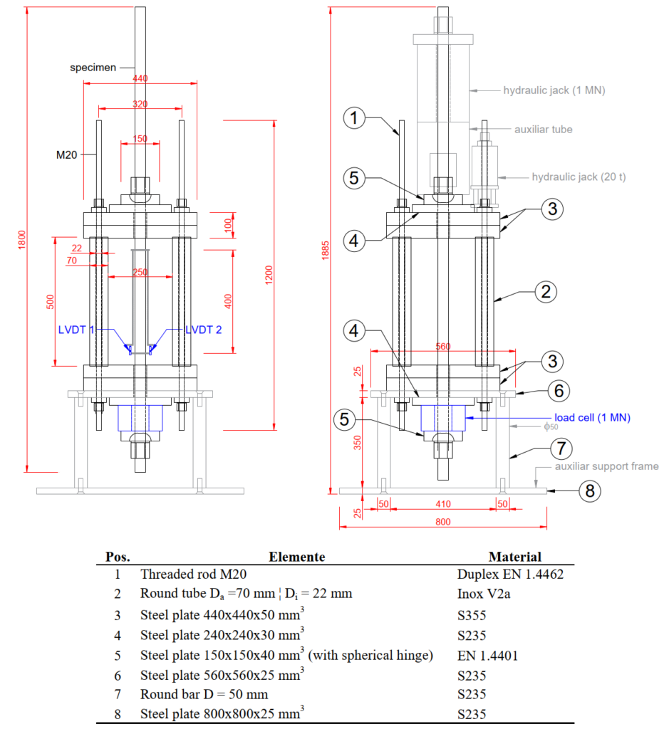
Figure 1 provides an overview of the test rig designed at ETH Zürich to conduct the relaxation tests on threaded rods according to ISO 15630-3:2019. The test rig consists of a main frame (pos. 1, 2 and 3), a support frame (pos. 6, 7 and 8), anchorage plates (pos. 4 and 5) and measuring equipment (two LVDTs and one load cell).
Relaxation at 1’000 hours
The relaxation tests of duplex threaded rods (M24, M27, and M30) were conducted at 1’000 hours with an initial tensioning stress () ranging between 0.72 and 0.82 of the average tensile strength ( ) obtained from the tensile tests performed on rods with no prior loading history (see the average for in Table 3). The initial stress, , varied between the specimens because, during the tensioning process, it was difficult to precisely control (but only estimate) the initial tensioning force (
 ), as there was an uncontrolled loss of force upon releasing the jack after the tightening of the nut.
Figure 2 illustrates the experimental stresses, relaxation, and deformation variation over time for duplex threaded rods M24, M27, and M30. Relaxation (considered positive) — defined as stress losses ( / ) — is depicted as the change in stress relative to the initial tensioning stress. The stress losses are shown by solid lines in graphs a.2 (M24), b.2 (M27), and c.2 (M30) in Figure 2.
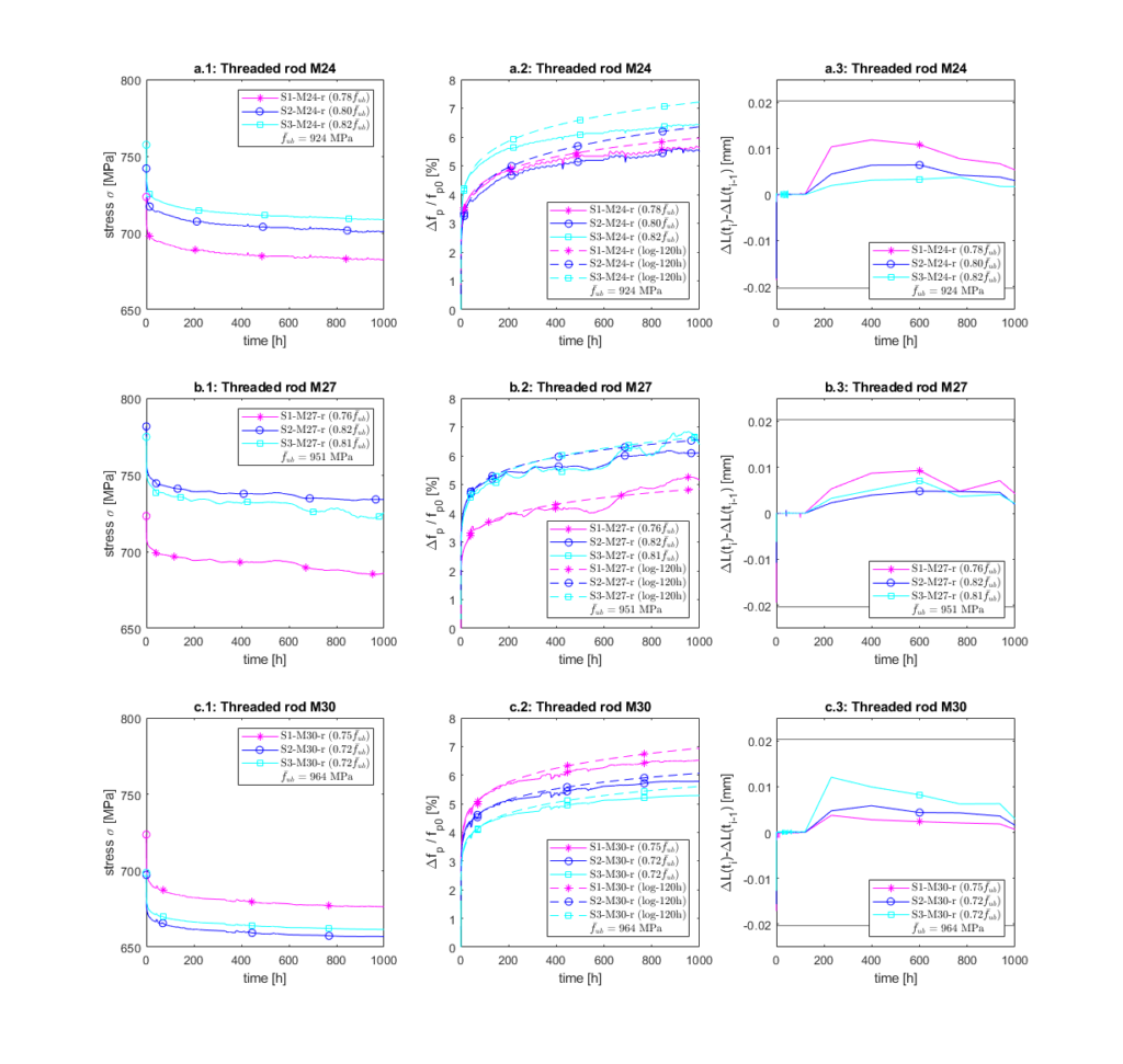
The deformation variation,  , shown in Figure 2 (a.3, b.3 and c.3), is monitored to ensure that the imposed deformation remains constant within the limits established in [3], “The variation of
  shall not exceed 5 × 10⁻⁵
  between two consecutive force measurements“. In the relaxation tests, the reference length is 405 mm; thus, the maximum admissible variation between two consecutive force measurements is ±0.0203 mm. The reference force measurements are indicated in Table 2 of reference [3]. The most significant variations (within permissible values) occur instantaneously in the first seconds, attributed to small slippages of the force holding nuts . The remaining variations are well within tolerance limits (±0.0203 mm), confirming the sufficient stiffness of the testing rigs for conducting relaxation tests.
Table 3 summarises the initial () stresses and the relaxation (prestress loss ratio),  /, at 10 minutes, 120 hours, and 1’000 hours of duplex threaded rods M24, M27, and M30, according to Figure 2. The average relaxation at 1’000 hours for the three metrics of threaded rods (M24, M27, and M30) is around 6% for initial tensioning stresses ranging from approximately 0.70 to 0.85 times . The evolution of relaxation over time resembles a logarithmic growth, with the most significant development occurring within the first 120 hours. About 30% and 80% of the relaxation at 1’000 hours occur within the first 10 minutes and 120 hours, respectively.
| Specimen | (1) | (1) | (2) | | / |  / / |  / / |  / / |
| [MPa] | [MPa] | [MPa] | [MPa] | [-] | [%] | [%] | [%] | |
| S1-M24-r | 911 | 716 | 797 | 725 | 0.78 | 1.9 | 4.5 | 5.6 |
| S2-M24-r | 911 | 738 | 791 | 747 | 0.80 | 1.4 | 4.3 | 5.5 |
| S3-M24-r | 950 | 731 | 809 | 757 | 0.82 | 2.3 | 5.3 | 6.4 |
| Avg. M24 | 924 | 728 | 799 | 743 | 0.80 | 1.9 | 4.7 | 5.8 |
| S1-M27-r | 941 | 713 | 809 | 723 | 0.76 | 1.6 | 3.7 | 5.2 |
| S2-M27-r | 970 | 720 | – | 782 | 0.82 | 2.6 | 5.2 | 6.1 |
| S3-M27-r | 942 | 709 | 855 | 775 | 0.81 | 2.3 | 5.0 | 6.4 |
| Avg. M27 | 951 | 714 | 832 | 760 | 0.80 | 2.1 | 4.6 | 5.9 |
| S1-M30-r | 996 | 783 | – | 724 | 0.75 | 1.9 | 5.4 | 6.5 |
| S2-M30-r | 938 | 777 | 855 | 697 | 0.72 | 1.8 | 4.9 | 5.8 |
| S3-M30-r | 957 | 794 | 830 | 699 | 0.72 | 1.5 | 4.4 | 5.3 |
| Avg. M30 | 964 | 785 | 842 | 706 | 0.73 | 1.7 | 4.9 | 5.9 |
| (1) According to the direct tensile tests performed on rods with no prior loading history (2) According to the direct tensile tests performed after relaxation tests | ||||||||
Relaxation at 120 hours and theoretical estimations at 1’000 h
As an alternative to the 1’000-hour relaxation tests, ISO 15630-3 [3] allows carrying out the tests for a reduced period of at least 120 hours. In this case, the relaxation at 1’000 hours can be extrapolated from the following semi-empirical equation:
(2) 
where / is the relaxation, generally expressed in percent;  is time, expressed in hours, and
  and
and  are coefficients. The coefficients and are obtained from logarithmic regression of experimental results from the first 120 hours. Figure 2 (a2, b2, and c2) shows the relaxation obtained from the semi-empirical Eq. (2), log-120h (dotted lines). It is observed that the log-120h curves correlate well with the experimental curves up to about 200 hours, but tend to overestimate relaxation at 1’000 hours.
The relaxation values at 1’000 hours, derived from the semi-empirical Eq. (2) and compared with experimentally obtained values, are outlined in Table 4. Notably, the 1’000predicted values tends to be slightly higher, exhibiting variations of 11.3%, 1.9%, and 5.8% (average values) for rods M24, M27, and M30, respectively. These differences remain within acceptable limits and are on the safe side to be considered in the post-tensioning design in structures.
| Specimen | / |  | |
| exp. | Eq. (2) | ||
| [%] | [%] | [%] | |
| S1-M24-r | 5.61 | 5.96 | 6.2 |
| S2-M24-r | 5.51 | 6.36 | 15.4 |
| S3-M24-r | 6.42 | 7.21 | 12.3 |
| x̄r | 5.85 | 6.51 | 11.3 |
| S1-M27-r | 5.15 | 4.85 | -5.8 |
| S2-M27-r | 6.10 | 6.55 | 7.4 |
| S3-M27-r | 6.39 | 6.65 | 4.1 |
| x̄r | 5.88 | 6.02 | 1.9 |
| S1-M30-r | 6.52 | 6.94 | 6.4 |
| S2-M30-r | 5.79 | 6.07 | 4.8 |
| S3-M30-r | 5.29 | 5.61 | 6.0 |
| x̄r | 5.87 | 6.21 | 5.8 |
Discussion and recommendations
Relaxation tests of duplex threaded rods resulted in average losses of around 6% at 1’000 hours, with their evolution over time resembling a logarithmic growth. The most significant development occurs within the initial 120 hours. Approximately 30% and 80% of the relaxation at 1’000 hours takes place within the first 10 minutes and 120 hours, respectively. However, based on comparisons made at the 10-minute mark during direct tension relaxation tests, it was observed that threaded rods previously subjected to loading and unloading cycles (in this experimental campaign, due to the relaxation tests themselves) exhibited 50% reduction in relaxation compared to rods with no prior loading history. This effect resulted in a 15% reduction in relaxation for preloaded duplex threaded rods at 1’000 hours. It is important to note that the results of the direct tension tests are not presented in this post.
In order to carry out an experimental campaign with the highest possible initial stresses in the threaded rods —so that their behaviour could potentially represent an application in the post-tensioning of structures—, these stresses were maximized. As a result, the rods were subjected to initial stress levels exceeding the minimum yield strength specified in the product’s technical documentation [4] ( > 700 MPa). Additionally, the loading and unloading process caused by the relaxation tests increased the yield strength of the threaded rods by at least 7% compared to the direct tensile tests on rods with no prior loading history (see Table 3), i.e., a minimum increase of 13% compared to the minimum yield strength given in [4]. It should be noted that the stress-strain curve of stainless steels shows non-linear behaviour even in the service range, resulting in a lower modulus of elasticity according to standardised estimation criteria.
Moreover, the average initial tensioning stresses were 0.78 times the average tensile strength of all series ( ), i.e.
  = 736 MPa, which is higher than the design tensile strength, fsd = 576 MPa (Eq. (1)), considering = 800 MPa (minimum tensile strength according to [4]).
By redoing the calculations for the example presented in Table 1, considering an initial post-tensioning stress of = 760 MPa (approximately 0.80 times the average strength of all series,  ) and an infinite time relaxation of 6%, the total post-tensioning losses are found to be 20%, in comparison to the 27% losses obtained in the preliminary calculations (Table 1). Post-tensioning losses around 20% are generally considered acceptable in the design of post-tensioned structures. It should be noted that the limitation of the design tensile strength given in Eq. (1) has been ignored, and the minimum yield strength defined by the technical documentation of the products [4] is exceeded in this new estimation.
However, their use is currently limited by their low yield strength, the design tensile strength according to SIA 263:2013 [2] (threaded rods considered as bolts) and the uncertainty of relaxation. Therefore, some recommendations or actions are listed below to overcome the limitations and promote the use of duplex threaded rods for external post-tensioning:
- By subjecting the threaded rods to a loading and unloading process (0.80…0.90 times the tensile strength, ) before the post-tensioning operations. This approach ensures an elastic behaviour during the post-tensioning phase, mitigating relaxation effects and enabling more precise tensioning control through elastic deformations.
- Ideally, duplex threaded rod products destined for post-tensioning should undergo a preloading process at the manufacturing facility. Furthermore, the technical documentation should define more precisely the mechanical properties of the product, including the recommended values of initial stress for post-tensioning (0.70…0.85·) and their corresponding estimated relaxation.
- Revision of the applicability of the design tensile strength estimation defined in SIA 263:2013 for duplex threaded rods destined for post-tensioning applications.
Please note that the recommendations and conclusions provided are derived from an experimental campaign limited to a small number of specimens. Therefore, these findings are preliminary, and a more extensive experimental campaign is needed to establish a more certain value of relaxation as a function of stress level and threaded rod diameter, and the influence of preload on the mechanical behaviour of the material.
Alejandro Giraldo Soto
References
- Schweizerischer Ingenieur- und Architektenverein (SIA), SIA 263: Stahlbau. Zürich: SIA, 2013.
- Schweizerischer Ingenieur- und Architektenverein (SIA), SIA 262: Betonbau. Zürich: SIA, 2013.
- ISO, “ISO 15630-3 Steel for the reinforcement and prestressing of concrete (Test methods) Part 3: Prestressing steel,” Geneva, Switzerland, 2019.
- Leviat AG, “Nichtrostende Bewehrungen für die Bauindustrie.” Jun. 2019.
Link zur deutschen Version: Überlegungen zur Entwicklung der Bauingenieurausbildung
Over the past few years, the modus operandi of higher education institutions has been disrupted in two distinct ways: first by restrictions on physical presence during the pandemic, and second, by rapid advances in Machine Learning (ML) and Artificial Intelligence (AI). The former disruption was abrupt, requiring swift adaptation to online teaching methods, while the latter is unfolding rapidly and unpredictably. Both developments challenge traditional approaches to learning, teaching and assessment. These shifts prompted me to reflect on my own educational journey, which coincided with an earlier disruption: the internet revolution of the 1990s and early 2000s. In this blog post1, I aim to frame those experiences within their specific temporal and institutional contexts, and to compare them with my more recent perspectives at ETH Zurich, both as a student and as a teacher.
My educational journey spans three public universities with long-standing traditions in Civil Engineering: undergraduate studies at the National Technical University of Athens (NTUA) from 1994 to 1999, postgraduate studies at the University of Texas in Austin (UT) from 2001 to 2003, and doctoral studies at the Swiss Federal Institute of Technology (ETH Zurich) since 2020, all with a specialisation in Structural Engineering. While these institutions share common ground in their academic focus, they differ significantly in several respects beyond their geographic locations. In the sections that follow, I offer a comparative narrative and critical reflection on the distinct educational approaches of each.
Size, budget and funding sources, tuition fees
A key distinction between the three universities lies in their academic scope: while NTUA and ETH focus primarily on STEM disciplines (Science, Technology, Engineering, and Mathematics), UT offers degrees across nearly all academic fields. This broader scope is reflected in the size of the institution—UT’s student population is roughly double that of NTUA and ETH—and also influences the structure of its curriculum, as will be discussed later.
In terms of budget and funding, two major differences stand out. First, the annual budgets of UT and ETH are roughly an order of magnitude higher than that of NTUA. Second, although all three institutions are publicly funded, their financial models vary: at NTUA and ETH, around two-thirds of the budget comes from state funding, whereas at UT, only about one-tenth is state-supported. This difference is reflected in tuition fees. While NTUA charges no tuition and ETH charges minimal fees, tuition at UT is significantly higher—especially for out-of-state students. These financial differences influence not only the composition of the student body but also, to some extent, students’ motivation and urgency to complete their studies.
Diversity
Diversity among students and faculty at each institution is shaped primarily by the language of instruction, but also by the research environment and employment opportunities offered by the institution and country. The following observations are based on my personal experience during my time at each university, with a focus on the Structural—and to a lesser extent, Geotechnical—disciplines.
At NTUA, where instruction was conducted entirely in Greek, nearly all students and professors were of Greek origin, with only rare exceptions. Most professors had completed their undergraduate studies at NTUA and pursued postgraduate education in the UK, Germany, or the United States.
At UT, the Master’s programme was notably diverse, with students from a broad range of countries, including China, India, South Korea, Japan, Kenya, Chile, Costa Rica, Turkey, Switzerland, and Greece. In contrast, undergraduate students were predominantly from Texas, a pattern driven by significantly lower in-state tuition fees. Most faculty members were U.S.-born and had completed their graduate studies domestically—many at the University of Illinois at Urbana-Champaign.
At ETH, German is the official language of instruction at the Bachelor’s level, while the Master’s program officially switched to English last year — although many Master’s-level courses had already been taught in English before the change. Consequently, around three-quarters of Bachelor’s students are Swiss, but the proportion of international students increases at the Master’s level and reverses at the Doctoral level, where Swiss students comprise roughly one-quarter. In Civil Engineering specifically, the share of Swiss students is somewhat higher than the ETH average. Faculty members in the Structural and Geotechnical Institutes are largely of European origin, with Swiss nationals making up a minority. Their educational backgrounds span Switzerland, its neighbouring countries, and beyond—including Greece, Israel, and the U.S.
In summary, the most diverse student body I encountered was at UT, while ETH currently hosts the most internationally diverse group of professors. By contrast, NTUA had the most homogeneous student and faculty populations.
Admission process
The admission processes for undergraduate studies differ markedly across the three countries, reflecting distinct educational philosophies and institutional structures.
In Greece, admissions are centrally administered by the Ministry of Education through nationwide exams. While the details have evolved over time, the core structure has remained stable for decades. In the final two years of secondary education, students select one of four academic tracks: (a) Humanities, Law and Social Sciences, (b) STEM, (c) Health and Life Sciences, or (d) Economics and Information Sciences. Each track grants access to corresponding university programmes. For example, entry into Engineering requires completion of the STEM track. Upon finishing secondary school, students sit for nationwide exams in four subjects; in the STEM track, these are Mathematics, Physics, Chemistry, and Language/Literature (the latter being common to all tracks). Students also submit a ranked list of preferred study programmes (e.g., Civil Engineering at NTUA). The Ministry then allocates placements based on exam performance, preferences, and available slots per programme. Universities have minimal influence over admissions beyond setting intake quotas and a minimum grade threshold. This process is largely anonymised and standardised, promoting fairness by relying on uniform national exams rather than variable school grades. However, its heavy reliance on a single exam day may favour strong test-takers and disadvantage others. It has also fostered a large private tutoring sector, potentially undermining the intended socio-economic inclusiveness of public education. Once admitted, students face no performance or time constraints, allowing flexibility in the pace of their studies and the option to work alongside their education.
In the United States, each university independently manages its admissions through a comprehensive application process. Students typically apply to multiple institutions in their final year of high school, submitting materials such as transcripts, personal statements, and optionally, test scores, recommendation letters, and records of extracurricular activities. Applicants generally declare a preferred major, which guides the review process, although changing majors later is often possible. This holistic approach aims to evaluate candidates beyond grades and test results, offering a more rounded assessment. Critics, however, argue that the process can lack transparency and may introduce bias. At UT specifically, about 75% of in-state positions are filled automatically by the top 6% of graduates from each Texas high school, a policy intended to promote diversity and represent regional demographics. The remaining positions are filled through holistic review.
In Switzerland, students who have completed secondary education within the country are generally granted direct access to the university programme of their choice. Regardless of background, admission to ETH is considered provisional and is confirmed only upon successful completion of the first-year examinations, which serve as a key academic filter. For international applicants, eligibility depends on their country of origin and may involve prior university admission in a related field or an entrance exam.
Study programmes
Study programmes vary considerably across the three universities, particularly in terms of format and duration. These differences can complicate transitions between institutions—especially for students wishing to complete undergraduate and graduate studies at different universities—and may lead to ambiguity regarding the relative standing of awarded degrees.
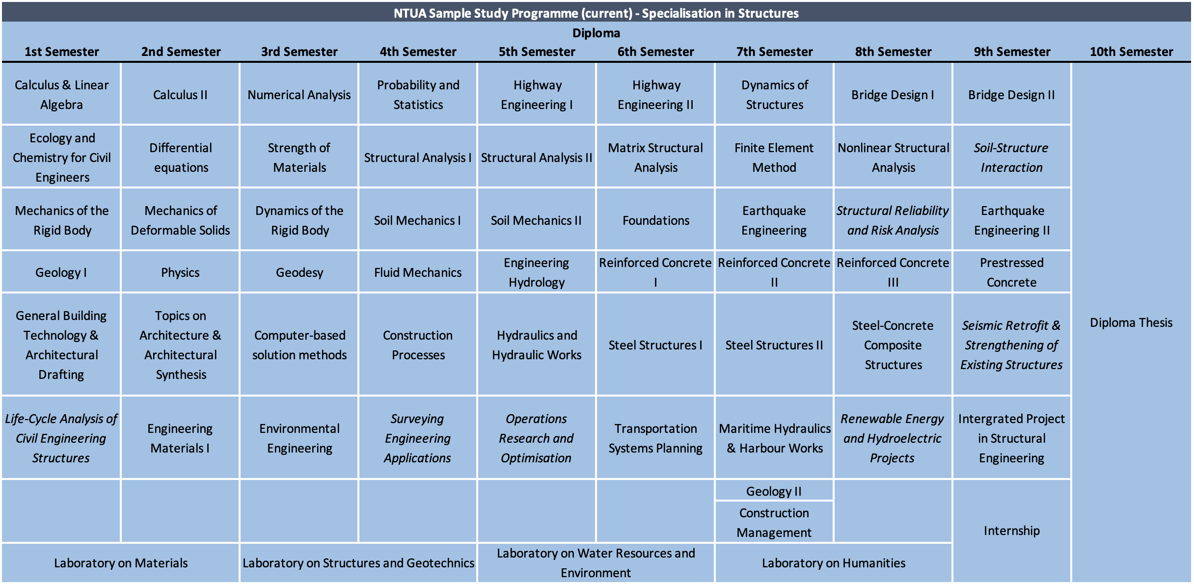
At NTUA in the 1990s, I completed a five-year programme leading to a Diploma in Civil Engineering. The programme comprised nine semesters of coursework and one semester dedicated to a Diploma thesis. After the sixth semester, students selected a specialisation—Structures, Transportation, or Hydraulics—guiding the final three semesters of coursework. The specific courses I attended within the Structures track are listed in Table 1.

The curriculum followed a three-phase structure:
- Semesters 1–4: Focused primarily on Mathematics and Mechanics, laying the foundation for later technical courses.
- Semesters 5–6: Offered core courses across all Civil Engineering disciplines, aiming to provide breadth and inform students’ specialisation choices.
- Semesters 7–9: Concentrated on the chosen specialisation, though still included some interdisciplinary content.
With the exception of the ninth semester, most courses were mandatory. Prerequisites were minimal, allowing students to take courses in flexible sequences. Lecture attendance was loosely enforced, except in laboratory sessions.
Comparing this with NTUA’s current programme (see Table 2), several updates are evident. While the overall structure remains similar, notable changes include:
- A condensed Mathematics and Mechanics curriculum, allowing earlier exposure to Civil Engineering topics.
- The introduction of a project-based course in the final semester.
- Annual laboratory courses in the first four years to reinforce theoretical content.
- A mandatory two-month internship in the final semester within a public or private sector organisation.
These revisions appear to address certain shortcomings of the earlier programme—more on this in the following section.
NTUA has no formal limit on the duration of study or on the number of attempts to pass a given course. Students can theoretically complete most coursework in any order, and performance is assessed in three annual exam sessions:
- Winter session: mid-January to mid-February
- Summer session: early June to early July
- September session: late August to late September (for retakes or grade improvements)
Graduates receive the Diploma degree, but must also pass an oral examination administered by the Technical Chamber of Greece to obtain a professional engineering license. This exam typically draws on the Diploma thesis; no supervised professional experience is required beforehand.
At UT, as is typical in the U.S., undergraduate studies span four years and culminate in a Bachelor of Science (BSc) degree. While many consulting firms prefer or require a postgraduate degree, it is still possible to begin a Civil Engineering career after earning a BSc. A sample BSc curriculum is shown in Table 3. The programme is structured around two types of courses: core courses, which provide a broad general education in subjects like history, literature, and government; and major courses, which align with the Civil Engineering degree. Students enjoy a degree of flexibility to tailor their studies, often with the guidance of an academic advisor. This may include pursuing a minor in another discipline. Summer breaks are typically used for internships, study abroad opportunities, or additional coursework.
Academic performance is closely monitored. If a student’s performance falls below a threshold, it may lead to academic probation or even dismissal. Attendance is usually mandatory and poor attendance can result in failing a course. Furthermore, most courses cannot be retaken more than once. Final exams take place in the week following the end of each semester. The autumn semester runs from late August to early December, while the spring semester begins in mid-January and ends in late April.
A comparison between the NTUA and UT undergraduate programmes reveals a relative lack of both breadth and depth in UT’s offering. This is largely due to the shorter duration of study and the significant portion of time devoted to general education. However, this gap is partly mitigated by two factors:
- Postgraduate education is the norm for those entering Structural Engineering.
- Professional licensure is tightly regulated in the U.S.
In the U.S., the licensure process typically begins with the Fundamentals of Engineering (FE) exam, usually taken during the final year of the BSc. Passing this exam grants Engineer-in-Training (EIT) status. To progress to Professional Engineer (PE) licensure, one must complete several years of supervised work under a PE and demonstrate progressive responsibility. Requirements vary by state but usually include references and a formal application to qualify to sit for the exam. Some states require a further level of licensure, such as Structural Engineer (SE) status, for engineers leading complex projects like high-rise buildings or long-span bridges. This also requires several years of supervision under an SE. Moreover, most U.S. states mandate continuing education to maintain licensure. Despite these regulatory safeguards, I firmly believe that a postgraduate degree should be a minimum requirement to practice Structural Engineering. As one UT professor remarked (hopefully somewhat in jest): “It is possible to graduate with a BSc degree in Civil Engineering left with the impression that the world is static and elastic.”
Graduate studies at UT are highly customisable, tailored to the student’s background and goals. My own Master’s studies in the early 2000s (Table 3) were flexible, in part because of the comprehensive foundation I had from NTUA. I was free to select courses, provided I included at least two outside the Structures specialisation. In contrast, graduates of a typical U.S. BSc would follow a more rigid programme with required courses in mechanics, structural analysis, and concrete and steel design. A key component of the programme was the Master’s Research, which was conducted alongside coursework and culminated in a thesis. Although students could opt out of the thesis by taking extra courses, most chose the research route. Many of the research projects were externally funded, covering tuition fees and providing a stipend to help with living costs.

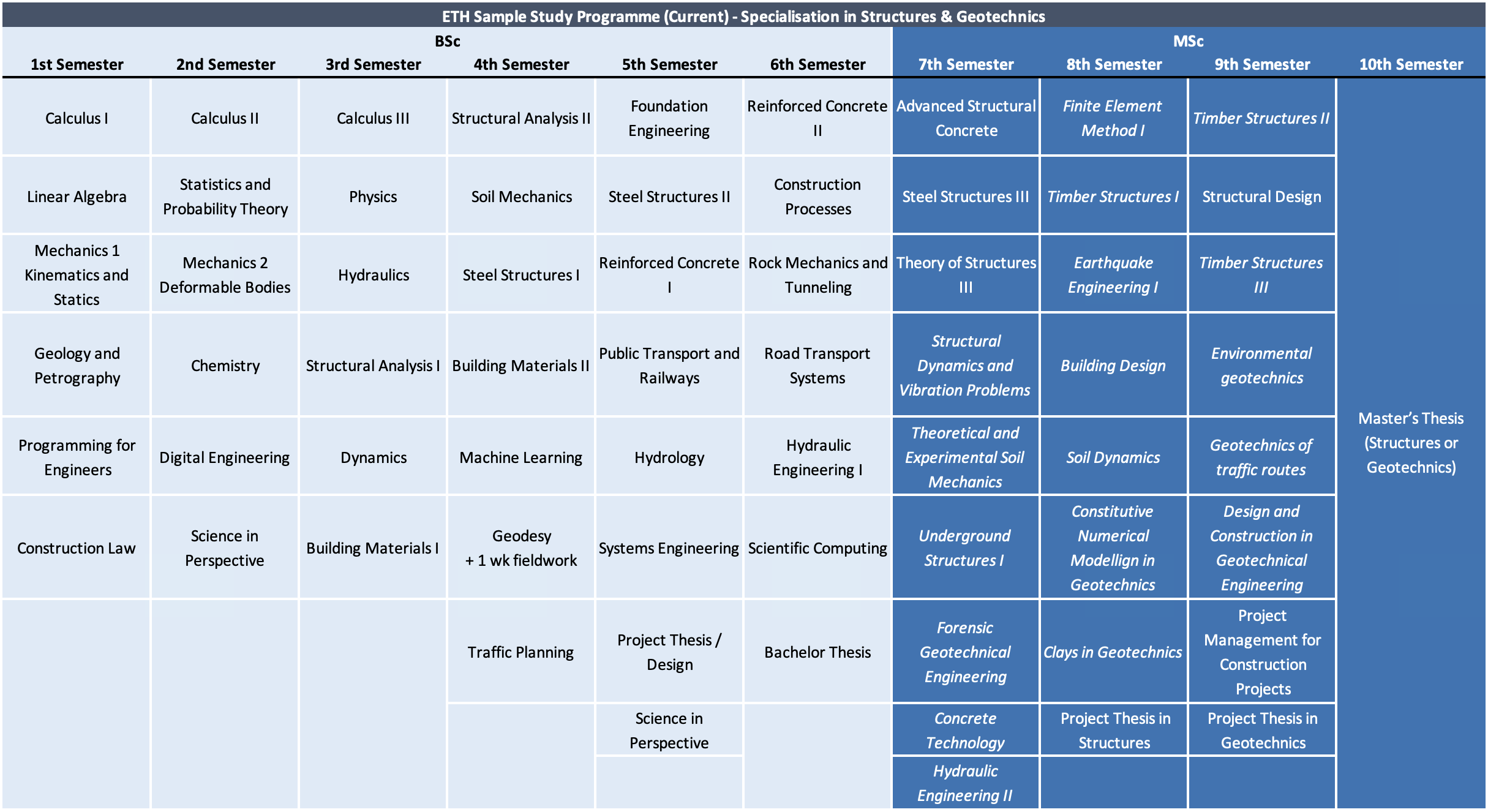
The study programme offered at ETH Zurich is philosophically quite similar to the one at NTUA, particularly in its strong technical foundation and academic rigor. A key structural difference, however, is ETH’s full implementation of the Bologna Process, which separates studies into a three-year Bachelor’s degree followed by a two-year Master’s degree. In contrast to the UT system, the Bachelor’s degree alone is not considered a professional qualification—this status is only attained after completing the Master’s. Nonetheless, many students choose to take a break between the two degrees to pursue internships or industry experience, a path that is both common and encouraged.
The BSc curriculum at ETH is composed almost entirely of mandatory courses, which are predominantly taught in German. These provide the theoretical groundwork necessary for Master’s studies. The programme culminates in a project-based thesis in the sixth semester. By contrast, the MSc curriculum is largely elective and taught primarily in English, allowing students to tailor their studies by selecting two out of six specialisation areas: Structures, Geotechnics, Transportation, Hydraulics, Materials or Construction Management. The courses, most of which are taught in English, are complemented by project theses and concludes with a research-focused Master’s thesis during the final semester.
Academic performance is strictly regulated. In general, students are allowed only one repeat attempt at a failed examination, and there is no option to retake a passed exam in order to improve the grade. These stringent assessment rules are somewhat balanced by the organisation of certain courses into blocks, where it is sufficient to achieve a passing average grade across the block. This means that poor performance in one course can be compensated by strong performance in another within the same block.
By comparing the three programmes, one could argue that—at least in theory—ETH offers a blend of the comprehensive curriculum structure of NTUA and the rigorous academic oversight characteristic of UT.
Personal reflections and retrospective evaluation
Overall, my experience at NTUA was positive and, in hindsight, I recognise that the programme provided me with the necessary foundation to pursue a successful career in Civil Engineering. Nonetheless, several aspects of the curriculum and its delivery detracted from that positive experience.
After two intense years in high school preparing for university entrance exams—primarily focused on mathematics and physics—I anticipated a change in perspective and an introduction to the applied world of Civil Engineering. Instead, the first two years at NTUA largely continued in the same theoretical vein, offering little to no contextualisation of how the material connected to engineering practice. This lack of integration was especially surprising given that all students in those classes shared the same disciplinary interest, which might have otherwise allowed for a more tailored, civil engineering-focused delivery of the content.
Moreover, the approach of “front-loading” theoretical knowledge before introducing practical applications felt counterintuitive. In high school, for example, our mathematical background often lagged behind the physics curriculum. Nevertheless, we managed to grasp core physics concepts—such as motion, energy, and electromagnetism—despite being limited in solving problems rigorously. Once we were taught more advanced mathematical tools, such as linear algebra or differential calculus, their practical relevance became immediately evident. In contrast, at university, this logic was reversed: abstract concepts were taught without accompanying applications. As a result, it was difficult to appreciate the utility of courses on computing (2nd & 4th semesters) and numerical methods (3rd semester), since most of the problems we had encountered up to that point had analytical solutions. To this day, I still struggle to understand the rationale for devoting an entire semester to the study of complex functions. This “front-loading” strategy had two main consequences:
- Some students lost interest in their studies altogether, while others treated these theoretical courses as box-ticking exercises, often deferring them to later semesters;
- By the end of the second year, most students did not “own” the material, which effectively forced professors of technical courses to revise their syllabi in order to re-teach essential prerequisites. As a result, we were “reminded” of statistics in the Hydrology course, of elasticity and Mohr’s circle in Soil Mechanics, and of strength of materials in the Concrete and Steel courses. While separating theory from applications may have some logistical benefits, I believe both student and professor time could be used more effectively through a more integrated and perhaps streamlined curriculum (further discussed in the next section).
This belief is further supported by the official course statistics, which often show pass rates below 15% in introductory mechanics courses—despite significantly higher pass rates (>50%) in later courses like Soil Mechanics or Steel Design, where the former is theoretically a prerequisite.
The workload and intensity of the programme increased significantly during the last three years. A typical semester included approximately 35 hours of lectures, exercises, or lab sessions per week. While attendance was usually not mandatory, it became increasingly essential. Assignments and semester projects—often completed during the Christmas and Easter breaks—added to the workload. A significant amount of learning took place during the month-long exam periods, as it was nearly impossible to stay on top of all courses during the semester. Consequently, only a small percentage of students graduated on time; most took six or seven years to complete the programme, a trend that likely persists.
One aspect I particularly appreciated was the range of practical projects we completed: a stretch of motorway, a small-scale hydraulic system, reinforced concrete residential and industrial buildings, a steel hangar, prestressed concrete and steel truss bridges, a timber house, and a harbour breakwater. These projects, although not fostering creativity, provided hands-on implementation of design and analysis principles. Notably, all calculations were done manually (except for some spreadsheets), and all drawings were hand-drafted.
Given Greece’s seismicity, many of the structural and geotechnical courses focused on earthquake-resistant design. Consequently, we studied dynamic and inelastic behaviour in depth, with strong emphasis on ductile detailing. Perhaps due to this seismic context, a conservative approach to conceptual design prevailed. Students were often steered toward simple and robust structural systems that could be analysed, designed, and built using relatively basic means. This likely aimed to ensure graduates would initially produce predictable and safe designs. However, this may have also contributed to the somewhat monotonous and uninspiring appearance of many Greek cities.
Some highlights of my studies included educational trips abroad—to Central Europe, Japan, and the northeastern US—during the third and fifth years. These experiences provided valuable exposure to different approaches in engineering practice, aesthetic values, construction materials, and environmental conditions.
Between my graduation from NTUA and the start of graduate studies at UT (1999–2001), the way information was accessed changed dramatically with the rise of the internet. Google had just launched (1998), the dot-com bubble was peaking, and the Web 2.0 era was beginning. At NTUA, information primarily came from professors, the university library, and a few nearby technical bookstores. My first systematic use of the internet was to research and apply to graduate programmes in the US. Upon arriving at UT, we were given a short course by a librarian on how to use online research tools—an experience that significantly transformed my study and research habits compared to the more sheltered academic environment at NTUA.
Many other differences between NTUA and UT were also striking. At NTUA, teaching was mostly one-sided and lecture-heavy, with little opportunity for active learning. Students worked individually, and studying mainly occurred right before exams, often with a short-term, memorization-heavy focus. Top grades were almost impossible to achieve; in some courses, even passing felt aspirational. In contrast, UT followed a more interactive teaching model. Lectures amounted to just 9–12 hours per week, supplemented by regular reading and mandatory homework, requiring three times as much effort outside class. Team projects were common. Because learning was continuous throughout the semester and midterms formed part of the assessment, final exams were often a mere formality for students who had worked consistently, where a cursory review of the material was normally adequate to achieve the maximum grade. Weekly seminars by industry professionals and alumni also provided useful exposure and networking opportunities.
Perhaps the most notable difference lay in the use of computers and industry standards in design courses. At NTUA, manual calculations were emphasized, and computer access was minimal. At UT, students were encouraged to use symbolic math software and had universal access to computers. Even at the undergraduate level, general-purpose finite element software was incorporated into structural analysis courses. Whereas NTUA taught fundamental behaviour alongside design code requirements, UT’s Bachelor-level courses focused on applying codes to design, reserving theoretical fundamentals for the Master’s level. This approach is partly shaped by industry expectations: US employers seek graduates—even at the BSc level—who are ready to contribute to design and documentation tasks using standard software and codes.
At UT, I also encountered more open-ended assignments, where students were tasked with conceiving structural systems under given constraints and evaluating alternatives holistically. My US-educated peers demonstrated qualities that stood out: effective teamwork, initiative, presentation skills, and confidence in proposing concepts—even when not always grounded in strong technical rationale. I attribute these strengths to the US educational system’s emphasis on initiative and innovation, early exposure to industry, and an overall entrepreneurial culture.
ETH’s teaching philosophy closely mirrors NTUA’s, with semesters structured around lectures and most learning concentrated before exams. Participation during the semester—lecture attendance or homework submission—is typically optional. ETH lectures tend to be even less interactive than those at NTUA, with students inclined toward passive rather than active learning. The shift to online, on-demand lectures during the pandemic may have further influenced learning habits. Innovation and critical thinking are highly encouraged at ETH, however. Students can engage in practice- and research-oriented projects, particularly during their Project and Master’s theses or through assistant roles in laboratory research.
During my involvement in teaching activities at ETH, primarily focused on bridge design but also supporting colleagues from the Department of Architecture in structural design courses, it quickly became evident that a significant emphasis is placed on designing structures with high aesthetic quality—far more so than at NTUA or UT. This can be observed by comparing the visual qualities of many Swiss bridges to the more utilitarian counterparts in Greece and the US. Additionally, concepts of efficiency and sustainability have moved to the forefront of the curriculum, a shift from the 1990s and early 2000s.
A key difference between UT and ETH is the role of doctoral students in teaching. At UT, teaching assistants mostly handled grading and labs, while professors supervised Master’s theses. At ETH, doctoral students are more heavily involved: they develop course material, lead exercises, design assessments, and supervise Bachelor, Project, and Master’s theses. Master’s students also support teaching at the Bachelor level. As a result, doctoral candidates at ETH typically gain far more teaching and supervision experience than those at UT. At NTUA, doctoral responsibilities varied widely depending on the supervising professor, but generally resembled the ETH model more closely.
Ideas for the future
Looking ahead to the future of civil engineering education, recent discussions have increasingly focused on technological developments in Machine Learning and Artificial Intelligence (ML/AI), and how these might shape both the teaching and practice of engineering. In my view, however, such advances only reinforce the importance of a strong foundation in fundamental concepts, taught through a classical curriculum rooted in engineering mechanics and theory of structures, with an emphasis on manual and intuitive calculation methods. While material science, construction processes, and computational tools will continue to evolve—transforming how we analyse, design, construct, and monitor structures—the core principles will remain essential and serve as the basis for meaningful innovation.
When designing future study programmes, it is important to distinguish between subjects best suited to academic instruction and those more appropriate for continuing education or on-the-job training. No academic programme can be fully tailored to the wide range of possible career paths, nor can it keep pace with every technological development. What it can do, however, is equip students with a deep understanding of fundamentals and cultivate a mindset of lifelong learning—enabling them to adapt to emerging challenges and embrace new methodologies with confidence.
Regarding course sequencing, I would question the conventional approach of “front-loading” the curriculum with theoretical courses in the early semesters, often delivered without real-world context. I believe it is both feasible and more engaging to introduce courses that do not require advanced mathematics or computational tools—such as introductory mechanics and statics, as well as topics in general building design, infrastructure elements, and associated construction methods—already in the first year. Doing so would expose students early on to the kinds of problems they will encounter throughout their studies, providing context for the more rigorous courses that follow. This approach has the potential to boost student engagement and improve learning outcomes.
Finally, given that most of us learn better by doing than by listening, I would support a relative reduction in lecture hours and a corresponding increase in active learning through assigned readings, lab work, and mandatory individual and group assignments. At the same time, I would shift the focus away from high-stakes end-of-semester exams, placing greater weight on continuous learning. This could be achieved by decreasing the final exam’s influence on the overall course grade and placing more emphasis on weekly assignments and semester projects.
In closing, I would be very interested to hear how my university experiences compare with those of others around the world and across different time periods, as well as to exchange thoughts on how civil engineering education might continue to evolve in ways that better serve our communities.
Albert Einstein
“Education is what remains after one has forgotten what one has learned in school.”
“Education is not the learning of facts, but the training of the mind to think.”
Disclaimer
Without loss of generality, the information and statistics provided regarding the aforementioned university programmes have been simplified and/or rounded for ease of comparison and readability. They may not reflect the most current data available at the time of publication of this blog post.
George Klonaris
- The cover image was created on 16.10.2024 with DALL-E. ↩︎
Link zur deutschen Version: Ein neuer Ansatz für Schalenelemente in der Finiten Elemente Analyse
In this blog post, I will focus on demonstrating the development of a novel so-called “hybrid machine-learning – finite element analysis” (hybrid ML-FEA) framework for shell elements. More specifically, I will focus on the data used to create this framework. In my last blog post, I have already elaborated on the motivation for using machine learning within the finite element analysis for reinforced concrete (RC) structures and shown a simple example of a surrogate model on a RC beam. In short: A neural network was trained to overcome the iterative task of determining the curvature based on the moment at any cross-section of a potentially cracked RC beam.
However, RC plates and shells (as opposed to RC beams) are often used in construction as fundamental components of large civil structures. Figure 1 shows three typical examples of RC shell elements in a bridge girder’s web or deck ((a), No. 1 and 3) or a standard ceiling slab ((b), No. 2). It is therefore important to investigate the usefulness of machine learning in a shell-element-based FEA to create a meaningful hybrid ML-FEA framework for RC structures that can be used to surrogate (or substitute) the standard FEA.
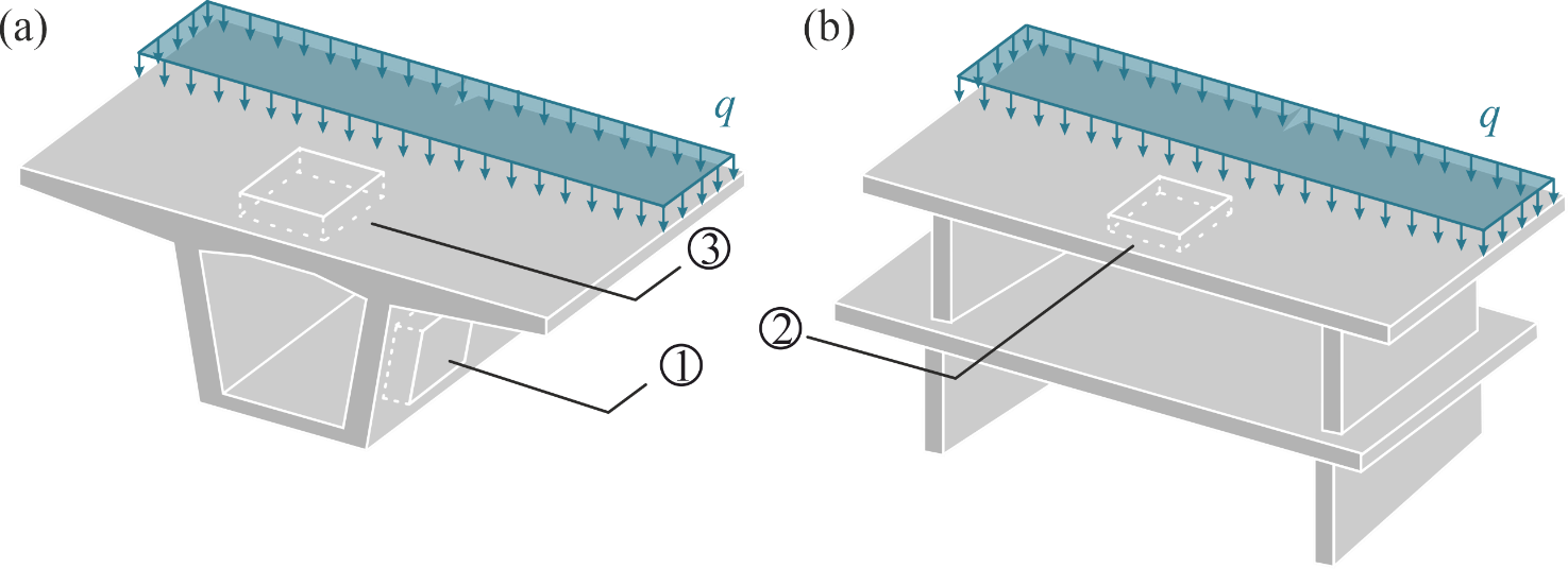
Compared to other machine-learning based surrogate models, this framework differs in the level on which it is applied within the FEA. Where other methods (e.g. Kuhn et al., see separate Blogpost) replace the entire FEA or try to find new material models by surrogating the stress ( ) – strain () relationship on a material point (e.g. Neural Metamaterial Networks by Li et al.), the hybrid ML-FEA framework developed here shall be applicable on the finite element level, meaning on the level of one shell element.
This implies that the ML model will surrogate the relationship between generalised stresses ( ) and generalised strains (
 ). These each comprise eight variables as shown below for a layered shell finite element used to model RC (Figure 2 and Equation 1): Three membrane force resp. strain components (
 resp.
resp.  ), three moment resp. curvature components (
 resp.
resp.  ) and two shear force resp. strain components: (
 resp.
resp.  ). In Equation 1,
  represents the generalised stiffness matrix, which relates the generalised strains to the generalised stresses.
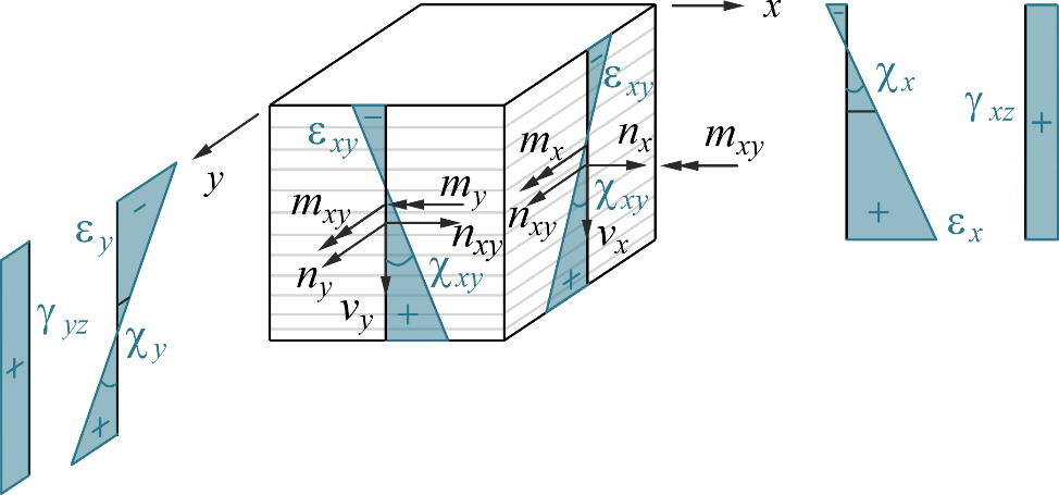
![\[\left\{\begin{matrix} n_x, n_y, n_{xy} \\ m_x, m_y, m_{xy} \\ v_{xz}, v_{yz}\end{matrix} \right\} = \left[\mathbf{D}\right]\left\{ \begin{matrix} \varepsilon_x, \varepsilon_y, \varepsilon_{xy} \\ \chi_x, \chi_y, \chi_{xy} \\ \gamma_{xz}, \gamma_{yz}\end{matrix}\right\}\]](https://concrete.ethz.ch/wp-content/ql-cache/quicklatex.com-d5d52354e3fa2da1d0d41ff7897df52f_l3.png "Rendered by QuickLaTeX.com")
Equation 1: Relationship between generalised stresses and strains.
In a first instance of investigating the hybrid ML-FEA framework for linear elastic layered shell elements based on the Reissner-Mindlin plate theory are analysed (Figure 2, Equation 1). Compared to the standard Kirchhoff plate elements, the Reissner-Mindlin shell elements also include out-of-plane shear components and are used for thick shell elements (Equation 1). Additionally, the layers of the shell element, modelled in plane stress, allow for analysing the strain and stress states of the individual layers separately. Hence, during the FEA, first the strain states and second the stress states are evaluated in every layer, the latter of which are then integrated across the height of the element to determine the generalised stresses (). The linear elasticity simplifies the problem for the first step of this investigation and results in a closed formulation for the matrix (i.e. can be calculated analytically). For a more complex material behaviour such as for nonlinear RC, this matrix is not available in closed form and needs to be determined iteratively. The matrix then depends on the different strain states of the layers in the shell element and, hence, on the applied material models (i.e. the material models applied in the cracked membrane model Usermat).
At this point, it is important to note that the linear elastic framework is simplified to such a big extent that a machine learning algorithm can neither improve the speed nor the accuracy of the problem. The reason for still implementing the hybrid ML-FEA framework for this case is purely to understand its application in a case where the standard FEA can easily be applied due to the analytical solution. The future goal is to extend this framework to more complex layered shell elements such as the ones used for the nonlinear analysis of RC shells.
To create the ML model, we need two main components: Data and a suitable ML architecture. For this blog post, I would like to focus on the data acquisition. In this example, the data is generated from the standard FEA simulation. The simulation takes quite some time, however once the data is gathered, a request to the ML-FEA hybrid framework will be at least as fast as the standard calculation (i.e. in this case the analytical equation). There are two different ways in which the data can be generated from the FEA simulation: Global sampling and local sampling (Figure 3). In the global case, different plate characteristics and boundary conditions are chosen with a Latin Hypercube Sampler (see also Wikipedia) and then simulated with a standard FEA. On the other hand, in the local sampling, the generalised strains are sampled directly with the Latin Hypercube Sampler. These then only need to be passed through the material model instead of the entire FEA to create the desired data. The final data set then consists of n sets of , ,  and . Even though these two sampling methods seem as though they should lead to similar datasets, the choice of the sampling strategy turned out to be a pivotal decision for the trainability of the ML model. As you can see in Figure 3, the data generated with local sampling leads to a much more evenly distributed data set, which leads to an increased accuracy in the predicted generalised stresses. This means that the ML model can be trained better and shows that every model is only as good as its underlying data.
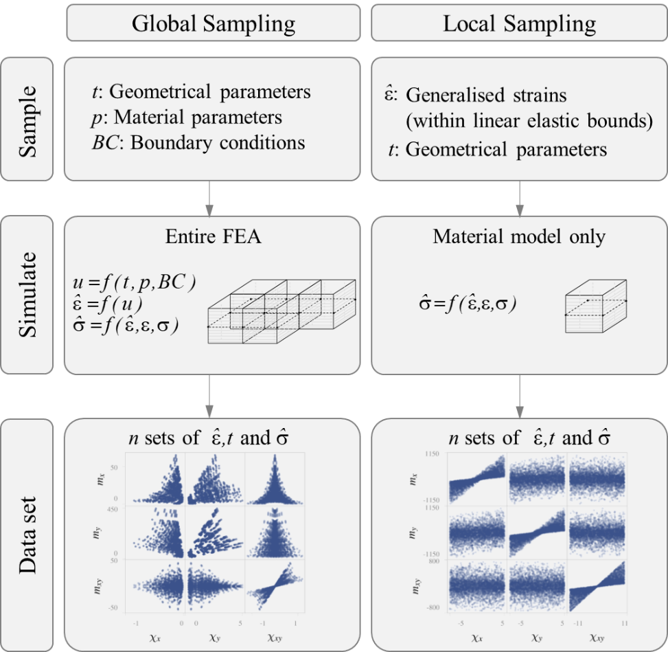 : Displacements;
  : a function).
You might be wondering why I did not use experimental data for this investigation, but instead had to first sample the data from the linear elastic material model. The reason for this is twofold: First, this example is very preliminary and used only for linear elastic cases, which would be difficult to extract from experimental data and also wouldn’t reflect the entire behaviour of a test specimen, i.e. only the uncracked part. Second, experimental data is scarce, particularly experimental data with known generalised strain and stress states. Currently, as a next part of the project, experimental data from shell element tests (e.g. from LUSET experiments) are gathered to try and create a data set for the nonlinear analysis of RC. However, chances are, that this data set does not comprise a distribution suitable for training a ML model on it.
After sampling the data from the linear elastic material model, different physics-based ML models were tested to keep the mechanical relationship  encoded in the ML architecture. A training with a Deep Operator Network yielded the most accurate test predictions and was therefore used for the linear elastic hybrid ML-FEA framework. More detailed explanations about the chosen architectures can be found in the paper [1]. This Deep Operator Network was then used in an example finite element calculation shown in Figure 4: A ceiling slab exposed to bending in one direction (Location 2 in Figure 1), consisting of 100 shell finite elements (10×10). Figure 4 outlines that the standard FEA (a) and the ML-FEA hybrid framework (b), in which each shell element is surrogated with the ML model, yielded very similar results, which is also underlined by the error calculation of a normalised root squared error (nRSE) (c). With this example, the application of a ML-FEA hybrid framework in the simplified linear elastic case was shown to be feasible.
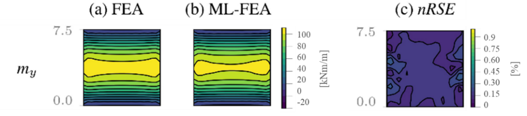
A paper was submitted to the fib Symposium taking place in June 2025. This paper will be made available within this blog post as soon as it is published online – until then, feel free to reach out to me, I’d be happy to explain more. Stay tuned for the next findings in machine learning for finite element analyses of reinforced concrete structures!
Vera Balmer
Literatur
Link zur deutschen Version: Wie maschinelles Lernen die statische Überprüfung bestehender Bauwerke unterstützen kann
Many bridges across Europe and beyond are reaching the end of their original design lifespan. This presents a major challenge, as the safety of thousands of ageing structures has to be assessed in a short amount of time. Asset owners have to strategically allocate resources for maintenance while balancing budget constraints, environmental considerations, and limited personnel capacity. However, traditional structural assessment methods are time-consuming, expensive, and therefore do not scale efficiently to large portfolios.
Recent advances in machine learning (ML) offer promising solutions. By creating data-based predictive models, we can accelerate initial assessments, prioritize structural interventions, and provide decision support for the structural assessment process.
In this blog post, we introduce a ML-based pre-assessment tool developed for reinforced concrete frame bridges – one of the most common bridge types in Switzerland. This prototype was created as part of an ongoing research project at our chair in collaboration with the Swiss Federal Railways (SBB). In the following sections, we demonstrate the tool’s application on a real-world example and discuss its practical implications and development potential. For those interested in the model’s creation, insights into the underlying methodology are provided at the end.
Application Example from the SBB Portfolio
To demonstrate how this tool can be applied in practice, we tested our ML-based pre-assessment tool on a real Swiss railway underpass from the SBB bridge portfolio. To estimate the structural compliance of an existing frame bridge, users can input or import the relevant bridge parameters into the web tool and generate predictions (see Figure 1) . To provide an initial estimate, the model only requires a few high-level geometric dimensions as input: span, plate thickness, and the bridge’s height and width. To achieve higher prediction certainty, users can also include additional structural details such as reinforcement layout, material properties, and loading conditions.
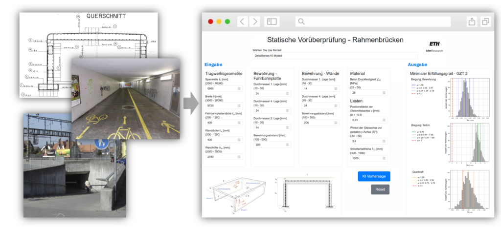
Figure 2 shows the results predicted by the ML model for the application example. The output consists of three predictive distributions representing the estimated compliance factors η for the inputted bridge structure, which indicate whether a bridge meets safety requirements according to the Swiss structural codes for ultimate limit state. The underlying data-driven model was trained and validated to generate predictions that closely align with detailed mechanical structural analyses.
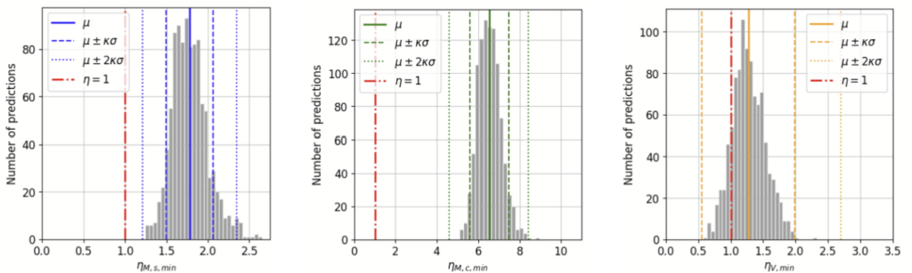
For this specific bridge, the ML model predicts that both bending verifications meet required compliance factors with a high level of confidence (η >> 1). However, for the shear verification, while the best estimate (i.e., the mean of the predictive distribution μ) remains above the threshold for structural sufficiency (η = 1), the model also indicates a degree of uncertainty. This is evident from the spread of the predictive distribution with a small part of the predictive distribution also falling below the threshold of 1. For this application example the tool, therefore, identifies the shear verification as critical. Given this uncertainty and the predicted value being close to the threshold of 1, the tool recommends the utilisation of detailed analysis methods to check structural safety, rather than applying simplified analysis methods, which may be too conservative to verify this structure.
The tool’s recommendation for a refined structural assessment was confirmed by a subsequent non-linear finite element analysis (FEA) of the structure, which validated the accuracy of the ML model’s compliance factor predictions for this example application. As a reference, the bridge had been previously assessed by an engineering firm using conventional linear FEA. This assessment resulted in insufficient compliance factors, leading to a recommendation for strengthening measures at an estimated cost of CHF 300,000. This shows the advantage gained with the prediction tool in this example. By using the ML-based pre-assessment tool, the appropriate refined analysis method was selected from the start. The non-linear FEA results ultimately confirmed structural sufficiency, preventing unnecessary, costly, and resource-intensive strengthening measures.
Practical Implications and Development Potential
Such a ML-based predictive assessment tool is not meant to replace detailed structural analysis but to serve as an efficient and economical first screening method. The application example showed that the model’s predictions provide decision support, helping asset owners determine the next steps for the structures within their bridge portfolio. It also helps structural engineers determine the appropriate level of refinement for the structural assessment of a specific structure. It is important to note that the tool’s predictions must always be interpreted with engineering judgment.
This prototype currently is applicable to simple concrete frame bridges. However, the method can be extended to also cover other bridge types, other countries’ structural codes and even additional factors such as damage assessments. Further development of the tool aims at efficient prioritisation of bridge assessment across large portfolios, efficiently allocate resources where they are needed.
How the ML model was developed
Based on the large frame bridge portfolio of the Swiss Federal Railways (SBB), we parameterised common concrete frame bridge structures, developed a parametric structural assessment pipeline and ran detailed non-linear FEA simulations, to create a dataset of structural compliance factors. Based on this dataset, we then trained a ML model (specifically, a Bayesian Neural Network [1]) to learn the mapping between bridge parameters and compliance factors (see Figure 3). This allows the model to interpolate the data in the high-dimensional parameter space and to make predictions for bridges that have not yet been analysed. Unlike standard neural networks, the Bayesian approach also estimates how uncertain a prediction is. Both the parametric pipeline used for data generation and the trained ML model, were validated on parameter studies as well as on existing structures (as seen in the application example above). The model’s predictive accuracy was tested on unseen data, and its uncertainty estimates were calibrated to ensure accurate confidence intervals.
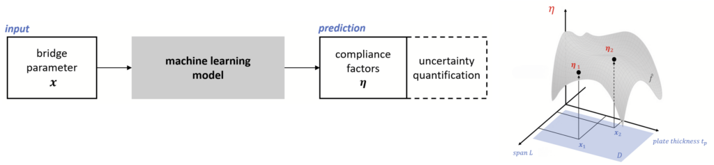
Want to Learn More?
Are you interested to know more? Do you have questions or comments to this work? Feel free to reach out to Sophia Kuhn.
Sophia Kuhn
Literatur
| [1] S. V. Kuhn, M. Weber, A. Binggeli, M. A. Kraus, F. Perez-Cruz, W. Kaufmann, Predictive structural assessment of concrete frame bridges with bayesian deep learning, manuscript to be submitted for publication (2025). |
Link zur deutschen Version: Grammatik für Fachwerkmodelle erklärt
Strut-and-tie models are a simplified, safe and typically manual design approach for reinforced concrete structures such as beams or walls. The iterative procedure to develop strut-and-tie models requires time and expertise from engineers which researchers have been attempting to reduce for decades. In my previous blogpost, I introduced two main approaches to automate the generation of strut-and-tie models for reinforced concrete structures and their advantages and drawbacks. Continuous topology optimisation aims to remove as much material as possible to minimise the weight or volume of a structure while meeting some structural constraints (e.g. yield strength of the reinforcing steel), where subsequently a skeleton truss needs to be derived from. However, this method has difficulty in incorporating fabrication aspects such as preferences for a regular layout or orthogonal reinforcement. Discrete layout optimisation aims to find a connectivity structure based on pre-defined grid-like nodes under certain constraints, but struggles to accommodate for user-defined adaptations. Due to these, both methods have not yet been able to gain widespread application in practice.
To tackle this research gap, we developed an approach based on rules and grammars. Inspired by theoretical computer science and formal languages, the concept of grammars has been already transferred to design, architecture and engineering applications. Domain knowledge or preferences are incorporated into rules that can generate diverse designs. We illustrate this concept with a simple example from formal languages. Typically, so-called context-free grammars consist of the symbols S (starting symbol), P (production rules), T (terminals, generation stops; here denoted with a rectangular shape) and V (non-terminals, generation continues; here denoted with an elliptical shape), all shown in Fig. 1. Suppose we want to generate a sentence, then each right-hand side of a rule can replace a non-terminal (left-hand side of the rule) in the generation process. We start with the rule S → subject-verb-object. As the next rule, we replace subject with “the student” and so on until we have no non-terminals left anymore and have generated the sentence “The student reads a book”.
This concept has also been applied in generative design. Our research interests lies in whether we can generate strut-and-tie models using such an approach, and whether these generated strut-and-tie models can be more practical than optimisation-based suggestions.
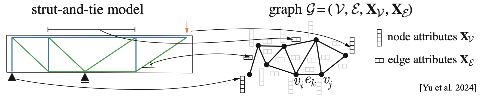
As a first step, a graph is chosen to represent the structural problem (Fig. 2). We are typically familiar with Euclidean data, which is represented in matrix form. However, when we want to capture more complex relationships within data (e.g. hierarchical structures or dependencies), we can use non-Euclidean representations such as graphs, groups or cells. Among these, graphs are advantageous for us because they efficiently represent structured data using nodes and edges. A strut-and-tie model can be easily transformed into a graph representation, where the nodes of the truss are the nodes of the graph and the struts and ties are the edges. Subsequently, we obtain a graph with the same connectivity structure as the truss. However, the usual matrix-based structural analysis scheme to obtain the forces of the edges is due to the graph representation no longer applicable. Therefore, we use the equilibrium condition at the nodes to find a static equilibrium. For the computational implementation, additional information such as the length or angle of an edge is added as node or edge attributes.
The main difficulty with the grammar-based approach is the derivation of rules. The set of rules should be sufficiently general to generate a variety of strut-and-tie models, but also specific enough to incorporate certain engineering judgement, such as adhering to minimum strut angles. To create these rules, some structural and geometric understanding is therefore required. Details of such rules can be found in our recently published journal paper [1] and some examples are shown in Fig. 3.
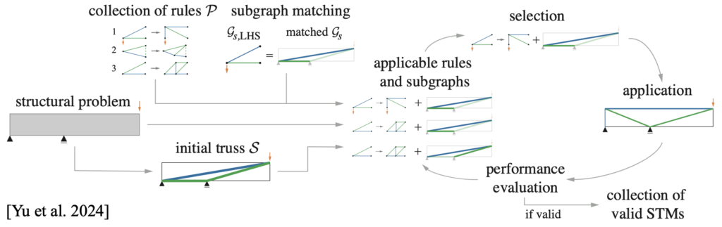
Once the rules have been defined, the procedure for generating strut-and-tie models is similar to the example for generating a sentence, see Fig. 3. An initial truss (the starting symbol) is derived from the structural problem, e.g. by connecting the boundary conditions. Unlike the example from formal languages, this generation does not directly have terminals and non-terminals. Edges can be fixed as terminals, to reduce the number of possible generations. Otherwise, based on the set of production rules, a subgraph matching algorithm1A subgraph matching algorithm tries to efficiently match a given subgraph to subgraphs of a graph. In this case, we want to find the left-hand side of a rule in the truss to know, where we can apply the rule. detects which left-hand sides of the rules can be found in the current truss. These possible combinations are suggested to the user, who can then choose which rule to apply. After transforming the truss with the chosen rule, performance metrics help to assess the quality of the truss, both in terms of validity (e.g. geometry, crossing of edges and strut angles) and suitability (e.g. reinforcement complexity and steel consumption) of strut-and-tie models.
The generation with grammars is illustrated for the deep beam with opening in Fig. 4, a common example2This example was also discussed in my last blogpost. from the literature. As a first step, a rule is applied to suspend the left node above the opening. The parameters of this rule can be adjusted to influence the position of the newly introduced node (compare the first step of each solution). By varying rules and parameters different strut-and-tie models can be generated. Both a simple and efficient design, such as Solution A with inclined reinforcement, and a complex design, such as Solution C, with orthogonal reinforcement can be generated using the grammar-based approach.
This and more examples [1] demonstrate that the grammar-based generation of strut-and-tie models allows for generating more practical strut-and-tie models as well as human-computer interation compared with the previously mentioned optimization methods3e.g. in Mozaffari et al. 2020. However, this generation might become cumbersome with increasing complexity of the strut-and-tie model and number of rules. We are currently exploring alternative computational or AI-based methods to navigate the design space with more automation and hope to update you later this year. If you have questions or suggestions, feel free to reach out to Karin Yu.
Karin Yu
Literature
| [1] Yu, K. L., Kraus, M. A., Chatzi, E., Kaufmann W. (2024). Grammar-Based Generation of Strut-and-Tie Models for Designing Reinforced Concrete Structures. Computers & Structures. Volume 305. 107549. doi.org/10.1016/j.compstruc.2024.107549 |
Link zur deutschen Version: Tragverhalten eines CFK-vorgespannten Bahnbrückenprototyps
After my last blog post on the production of Switzerland’s first CFRP prestressed railway bridge prototype, the “prototype” project was essentially over for me, and I was looking forward to doing some serious science from my office chair again – preferably something including AI. Over the course of the summer, however, the question of what to do with this somewhat clunky thing crept back up on us: Especially given its superior durability properties, it couldn’t stand around in our lab forever. Put it up in the coffee room as a vertical flower box? Launch it into space to market our flagship sustainability project? With a weight of 10 t, the prototype would only be marginally heavier than the red Tesla that has been doing its rounds there for years… After both ideas had to be scuttled primarily due to excessive internal ETH bureaucracy (ever tried to get a permit from a federal office for launching a rocket?), the idea of testing the prototype for its load-bearing behaviour came up. Pretty wild, someone would have had to build a test rig with a capacity of 3 MN and have installed optical fibres for strain measurements on the reinforcement and prestressing already during the production of the prototype…
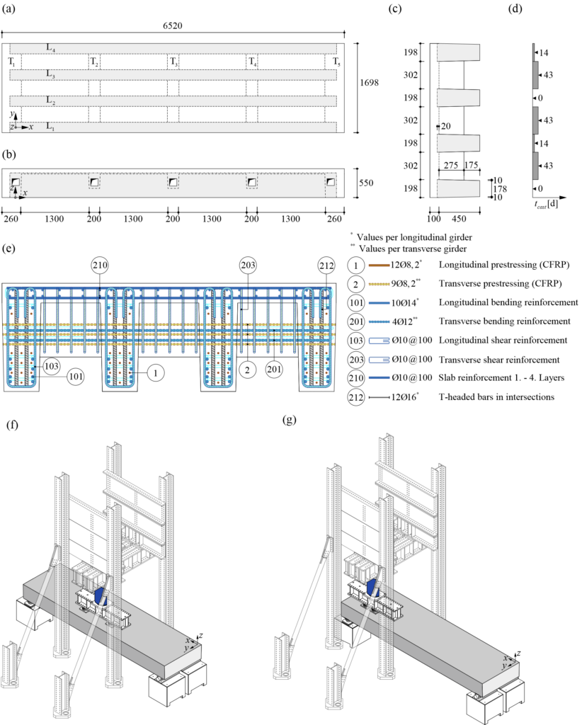
In addition to demonstrating the feasibility of the production, the aim of testing the prototype was a “proof of concept” regarding the load-bearing behaviour of the material “CFRP-prestressed steel-reinforced concrete” and its suitability for railway bridges. The following questions were therefore of central importance:
- Does the anchorage of the pretensioned CFRP rods work as anticipated via bond with the concrete? In particular, does it also function under cyclic loading and loads positioned in the vicinity of the supports?
- How does the composite material behave in the ultimate limit state? Do we achieve the desired bending failure mechanism “concrete failure at yielding of the reinforcing steel” and a certain plastic deformation in the reinforcement despite the brittle CFRP?
- How does the prototype behave under loads close to the support, which type of shear failure occurs? What compression field inclinations can be assumed in the shear verification of high-performance concrete with CFRP-prestressing?
Short disclaimer: I cannot go into these questions in detail in this blog post. For detailed test analyses and interpretations, interested readers are referred to our scientific publications (e.g. here). But first things first: Figure 1 provides an overview of the prototype and the test setup of the bending and shear test. The prototype consisted of four CFRP-prestressed longitudinal and three transverse girders (in the span) and was initially subjected to four-point bending. The loads were applied to the second of four longitudinal beams, thus eccentrical in the cross-section. After 60’000 load cycles at three different load levels, the specimen was tested to failure, whereby the failure mechanism was concrete crushing at yielding of the reinforcing steel with subsequent (clearly audible) rupture of the first CFRP rods at mid-span. The test rig was then slightly modified and a shear test was carried out in an intact area of the specimen, which was rotated by 180° before reinstalling.
Videos 1 (time-lapse recording) and 2 (end of test) show excerpts from the bending test. It is important to emphasise that despite the concrete crushing in the bending compression zone (see Video 2), which extended over almost the entire width of the specimen, and despite the rupture of individual CFRP rods (Video 2 with sound), no total collapse of the prototype took place.
In combination with Figure 2 (load-deformation in bending and shear tests, image of shear failure), the videos provide insight into some, but not all, of the questions formulated in the beginning:
- The prestressing remained intact during the entire test series, which is demonstrated by the “re-erection” of the specimen after the bending test (see Video 1). Unfortunately, it was not possible to conclusively determine the extent to which the anchorage zones of the CFRP rods had extended due to the cyclic loading and the shear load, as the optical fibres on the pretensioned CFRP rods of the longitudinal beams did not work during the tests.
- The intended bending failure mechanism was achieved. In three out of four longitudinal girders, the reinforcing steel was yielding at the end of the bending test, which resulted in a redistribution of forces in the specimen. Figure 2 (a) shows (i) how all four longitudinal girders were activated and (ii) the significant deformation capacity after reaching the maximum load (failure of the concrete compression zone). At this maximum load, there was no significant force drop in the deformation-controlled test setup. Instead, the system was able to deform considerably under approximately constant load before the test was stopped.
- All four longitudinal girders were also activated under loading close to the support, as can be seen in the load-deformation diagram of the shear test in Figure 2 (b). As expected, the shear failure occurred in the loaded girder L2, with a shear force in the longitudinal girder of approx. 900 kN. This leads to the conclusion that the stirrups were yielding, but the failure occurred in the concrete, as shown in Figure 2 (c), at a fairly steep compression field inclination of about 35-40°. Consequently, there were no “rotating cracks” with flat inclinations at the end (compare to admissible compression field inclinations in prestressed structures according to SIA 262), which is not unusual for high-performance concrete due to its low crack roughness.
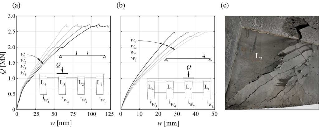
From the project team’s point of view, the proof of concept was successful. The system behaves as anticipated in bending, and the reinforcing steel brings a certain plastic deformation capacity into the system. The prestressing is robust but needs to be investigated in further detail. The same applies to the shear behaviour. What does that mean? As part of the current project phase “Scientific work” (phase 3 of 5 on the way to the actual construction of a CFRP-prestressed railway bridge on the SBB network), further tests are pending; the static and cyclic shear tests on individual CFRP-prestressed T-beams will be particularly interesting. In parallel to the test campaign, we are now developing mechanical models and verification concepts. It also means that the AI-thing will have to wait… stay tuned!
Andreas Näsbom
Literatur
| [1] | A. Näsbom, K. Thoma and W. Kaufmann, “Construction and testing of a CFRP-prestressed railway bridge prototype”, in IABSE Symposium Manchester 2024, Manchester, Apr. 2024. |
Link zur deutschen Version: 3D-Apps mit AR-Funktionalitäten für die Lehre im Stahlbetonbau
Introduction
Learning the fundamentals of structural engineering involves not only the understanding of mathematical formulae and mechanical models but also their interaction with the real-world 3D space. Our chair had a good experience with the introduction of web applications to help our students understand the main principles taught in our structural concrete classes. These applications, though, mainly focus on the abstract representation of the content through 2D drawings, diagrams and text. Additionally, they offer the possibility to interact with the underlying mechanical models by altering the geometric, material or other properties using sliders as well as textual input fields. While this approach is adequate for many different teaching contents, as shown by 17 applications already in use for our bachelor`s classes, we also found examples that would benefit from a different presentation style. Three drawbacks were identified that hinder the current approach from being adapted for some examples. These are:
- Representation of concepts in an abstract manner using 2D drawings or diagrams. This can complicate the students’ ability to relate the concepts shown to real-life examples.
- Many different input options like sliders, text fields and multiple output figures can be overwhelming for the students.
- The apps are written within different programming environments, which can be a hurdle for inexperienced teaching assistants.
To address these three points, the new generation of apps is based on the following three ideas:
- The representation of geometry in 3D space both in a virtual environment and also anchored in the real world using augmented reality (AR) functionality.
- A clear user/student journey through the application to avoid overwhelming the students by the complexity of the model.
- A simple implementation concept in the backend that enables the easy manipulation of existing examples and the quick creation of new examples.
It has to be emphasized that the newly developed framework for 3D–AR–Apps is not meant to replace the current collection of apps used at our chair. Instead, the goal is to apply these in cases where the current generation of apps is not suitable.
Prototype
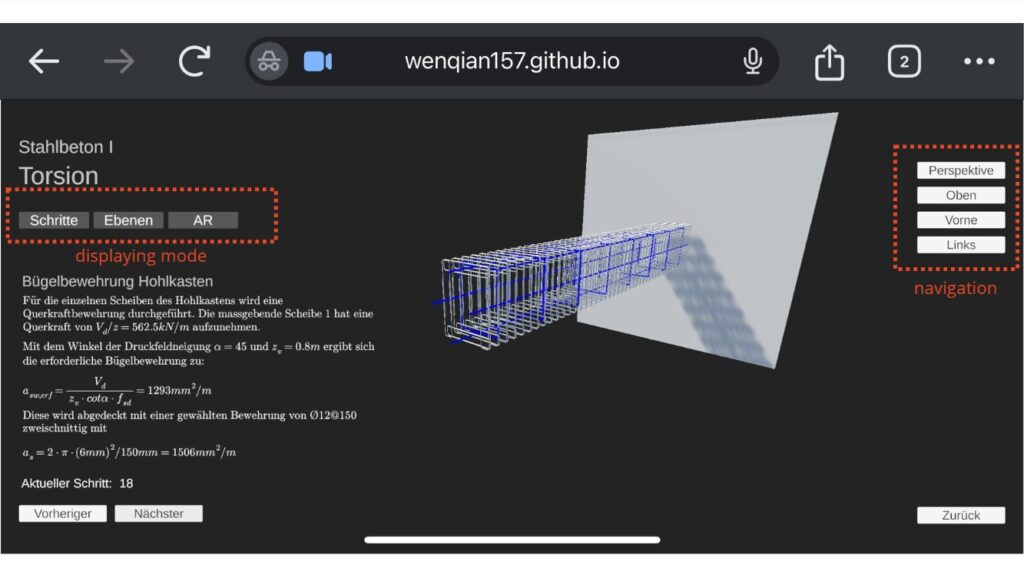

Our first example is based on one of the exercises in the module “Structural Concrete I”, dealing with the design of a torsion beam using strut and tie models. The User can access the app with most mainstream browsers on either a mobile device or a computer. To get started, simply visit the provided link or scan the QR code with the camera.
Once the app is running, you can explore its features through the user interface.
For the AR function, grant camera access when prompted, then scan an Aruco 6×6 marker to utilize augmented reality features.
Backend Implementation Framework
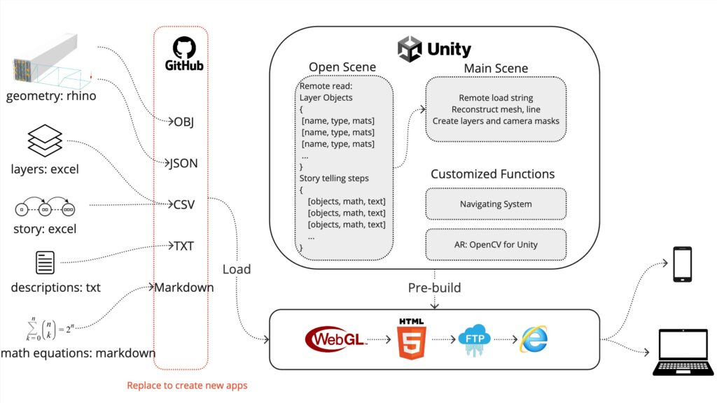
The main idea of the framework is to be easily useable and adaptable for app creators who are not familiar with Unity. Therefore, widely used file types were chosen as the input. In the current state of the project implementation, these include the following raw input files:
- 3D-geometry (.3dm)
- Layer information (.xlsx)
- Story information (.xlsx)
- Step descriptions (.markdown)
The framework consists of three main parts. The first step involves converting all raw input files into formats that are easily communicated via the internet, such as OBJ, JSON and CSV. The second step entails designing a Unity project to receive these materials and deserialise them into 3D geometry, diagrams or math equations. A customised navigation system for mouse and touch input in a browser environment has been developed, enabling users to experience the content in 3D space. Additionally, an AR implementation is introduced to help students understand the geometry in the physical space. The third step involves compiling and deploying this app as a web application, which is then hosted on a web server for users to access.If you want to know more about the process of creating a new app, feel free to have a look at the readMe file.
Conclusion
The current version of the app represents the culmination of the team’s ideas and efforts over the past few months. Your participation in testing and providing feedback is crucial for optimisation and for the next phase of the project. We aim to test the stability and user-friendliness of the interactive features, as well as ensure compatibility with a variety of devices before releasing a robust version to students. The main goal of the next phase is to scale up the project. Theoretically, new applications can be created by simply replacing the remote materials.
We invite you to test the first prototype of the app on our website and would be very happy if you would share your thoughts using this feedback questionnaire.
Paul Merz and Wenqian Yang
Link zur deutschen Version: Auswirkungen von Anforderungen bei Betondecken
Almost a year ago, a blog post was published explaining how digital fabrication could foster the application of structurally efficient concrete floor slabs to reduce the construction industry’s negative ecological impact. Since then, we have carried out a study on floor slab requirements in the same research project and are happy to present some selected results in this blog post. The study was presented at the fib PhD Symposium 2024 in Budapest (see the blog post on that conference here) and awarded a special mention. More details can be found in the conference paper titled “Correlations of requirements and performance metrics for concrete floor slabs”, authored by Rebecca Ammann (the author of this blog post), Dr. Karel Thoma, Prof. Dr. Jaime Mata-Falcón and Prof. Walter Kaufmann.
When studying literature on structurally efficient concrete floor slabs, it is often questionable if the potential sustainability enhancements found in academic works are achievable in real-life applications. This is not only because the regular floor layouts considered in many research works are not fully representative of real-life projects, but also because requirements that may govern the design in real life, such as fire safety or sound insulation, are often not considered in academic works. However, such requirements can be decisive for the development and study of new (digitally fabricated) structural concepts (which is a goal of this research project) and limit the efficiency of conventional concrete floor slabs. Thus it is crucial to study the impact of these requirements for concrete floor slabs systematically.
As there are numerous requirements and because the implications of a requirement are highly dependent on the chosen case study, we developed a data generation pipeline for this purpose. With this pipeline, the impact of different requirements can be assessed quickly, automatically and objectively for a wide range of case studies. A schematic visualisation of the data generation pipeline, implemented in Python with an interface to the software RFEM 6, is given in Figure 1: The input data consists of the geometry of the floor slab, the loads, the material properties and the requirements to be considered. For each set of input data, a finite element (FE) analysis is carried out, and a reinforcement design is found iteratively based on the FE results. Once a valid design fulfilling all ultimate limit state (ULS) and constructability verifications is found, the respective performances are calculated, and the requirements are checked.
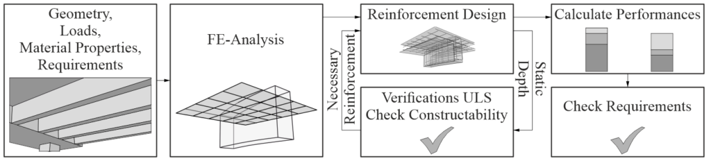
We applied this data generation pipeline to a simple case study with a square floor layout and two structural systems (solid slabs and ribbed slabs), as shown in Figure 2.
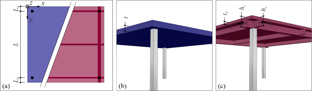
To limit the scope of this blog post, only the results regarding the serviceability requirement that limits the maximum deflection w are presented below. Further results can be found in the conference paper.
As the geometry of the concrete floor slab is an input parameter in the data generation pipeline and the optimal geometry is not known beforehand, numerous configurations were analysed. In Figure 3, the performances (relative cost and Global Warming Potential GWP) of all valid configurations are shown for a span L of (a) 5 m and (b) 8 m. The minimum cost and GWP for different spans and requirements regarding the deflections are shown in Figure 3 (c) and (d), respectively.
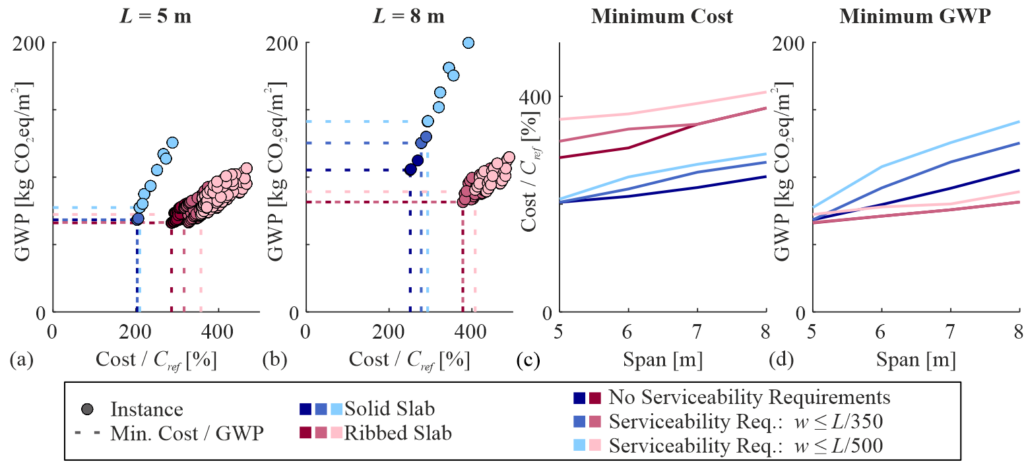
For flat slabs (shown in blue), limiting the maximum deflections w leads to a considerable increase in GWP and – to a lesser extent – costs, especially for larger spans (comparison of light blue line to dark blue line for given span). In contrast, for ribbed slabs (shown in pink), the increase in cost due to limiting the deflections (comparison of light pink line to dark pink line for given span) is more significant than the respective increase in GWP.
While the presented absolute values are subject to the limitations of the simple case study, we could show that with the data generation pipeline, it is possible to quantify the significant effects of requirements such as serviceability on costs and GWP. In a follow-up study, this data generation will be applied to real-life projects provided by an industry partner, taking into account more requirements and performances. As requirements are generally specified at a very early design stage without assessing their implications, we hope to raise awareness and foster the discussion on the huge impact these requirements can have with our work.
The generality of the data generation pipeline allows us to apply it to other problems, such as the comparison of different structural floor systems or assessing the applicability of a specific structural floor system to various projects – the possibilities are countless, and we look forward to updating you about our progress in due course.
Rebecca Ammann
Link zur deutschen Version: fib PhD Symposium Budapest 2024 – Ein Erlebnisbericht
At the end of August, I participated in the fib PhD Symposium. The fib (Fédération internationale du béton or The International Federation for Structural Concrete) organised this conference for the 15th time. Only PhD and doctoral students who deal with concrete in the broader sense presented their work at this conference. (However, there are conferences organised by the fib and other associations aimed at practitioners and researchers). The more than 150 presentations were divided into five parallel sessions, meaning that throughout the three days of the conference, there were always five presentation sessions running simultaneously. The variety of topics is illustrated by the titles of the individual sessions:
- Structural analysis, modelling and design
- Assessment and structural health monitoring
- Innovations in metallic and non-metallic reinforcement
- Durability of existing concrete structures and durability for future structures
- Innovations in concrete and concrete technology
- Bridges, reservoirs, dams, tunnels and road constructions
- Sustainability of materials and structural systems, including heritage concrete structures
- Life cycle assessment and design, rest life
- Composites for strengthening concrete structures
- Maintenance, retrofitting or strengthening of concrete structures
- Digitalisation – 3D concrete printing
- Buildings and shells
- Structural reliability and risk analysis
Participants from 72 universities across all continents were represented, with the majority coming from Europe.
In the first part of my blog post, I will share four presentations/ideas that I found interesting (and did not come from our research group). In the second part, I will report on the social aspects of the conference, which, in my opinion, are just as valuable as the technical inputs.
Part 1 – Interesting presentations
Conferences are not only there to disseminate your work but also to get inspired by the work of others and to honour their work. In that spirit, the following presentations have left a lasting impression on me:
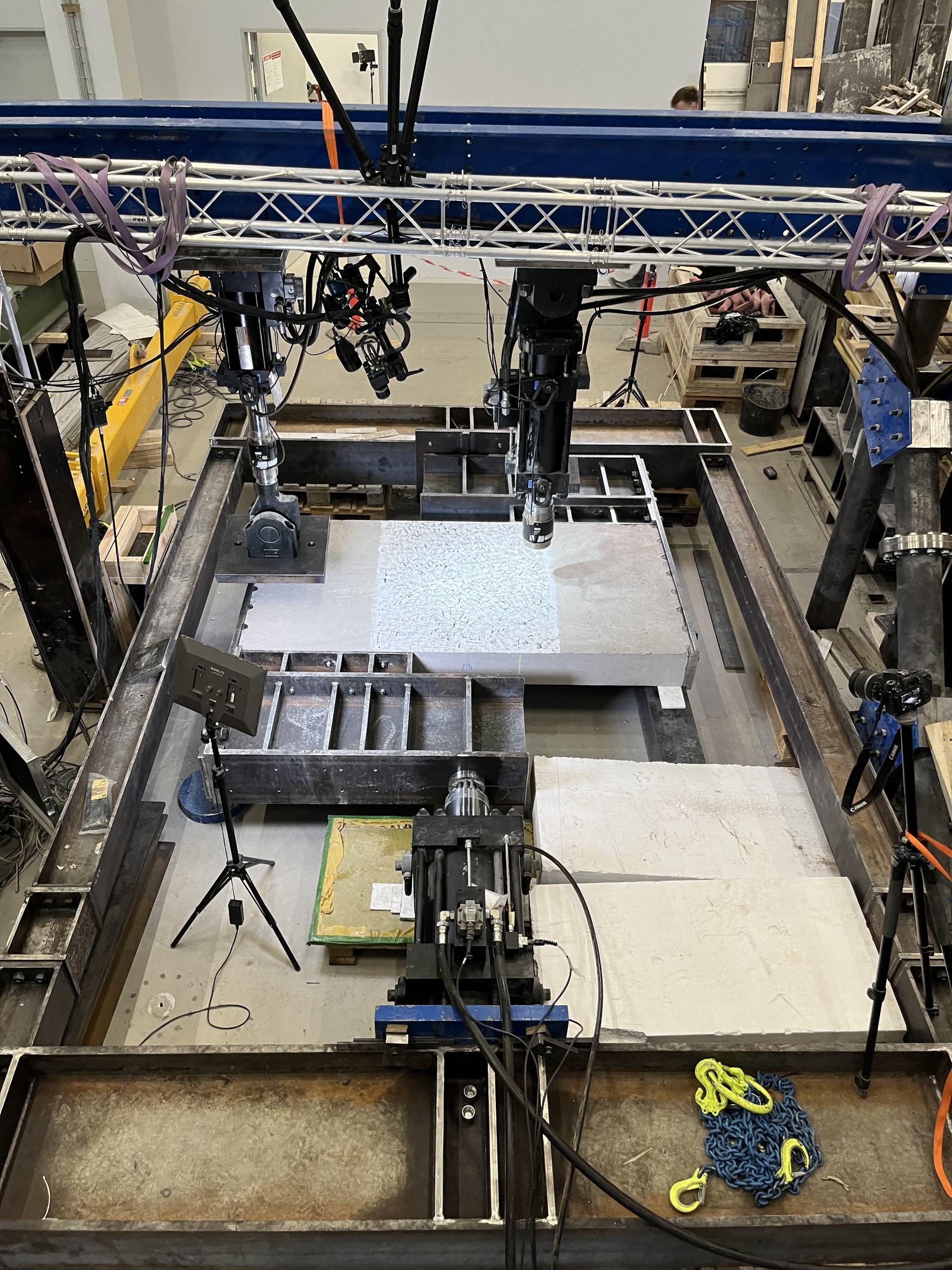
Jens Skovgaard Larsen (Univerity of Southern Denmark / COWI [Industrial PhD Student]; co-authors: Henrik Brøner Jørgensen and Søren Gustenhoff Hansen) has in his first year as a PhD student already conducted several large-scale tests on a test setup he developed himself (see Figure 1). These tests investigate the interaction of in-plane and out-of-plane shear in reinforced concrete slabs without shear reinforcement. He also plans to experimentally examine how moments affect the interaction of in-plane and out-of-plane shear.
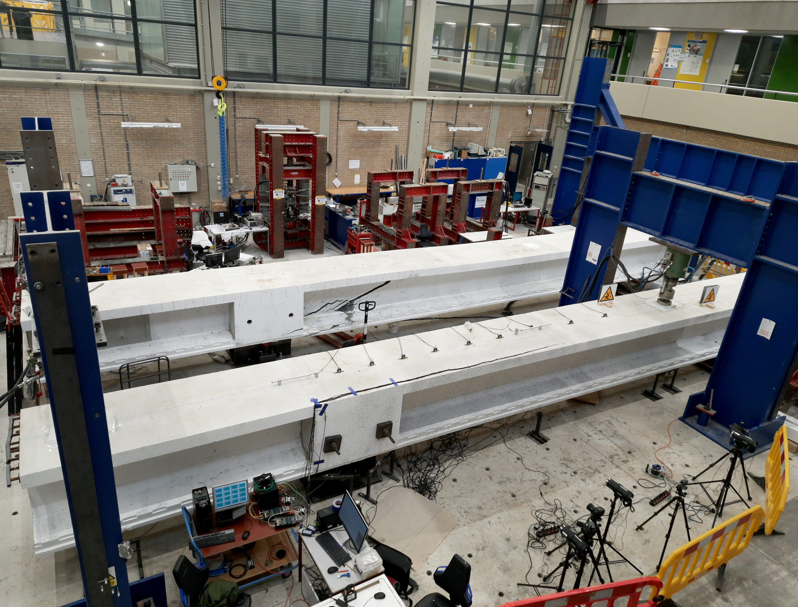
Mohammed Sirage Ibrahim (TU Delft; co-authors: Mauro Poliotti, Yuguang Yang und Max Hendriks) has tested over twenty 15m long prestressed concrete girders for shear (see Figure 2). This project is based on the fact that many existing bridges in the Netherlands consist of prefabricated prestressed single-span girders that have been made continuous girders. Among other things, questions arise regarding the shear behaviour of these girders. I also find the blind-prediction contest that was carried out on this project very interesting. Emilia Andrade Borges (TU Delft) will continue the project and conduct further tests.
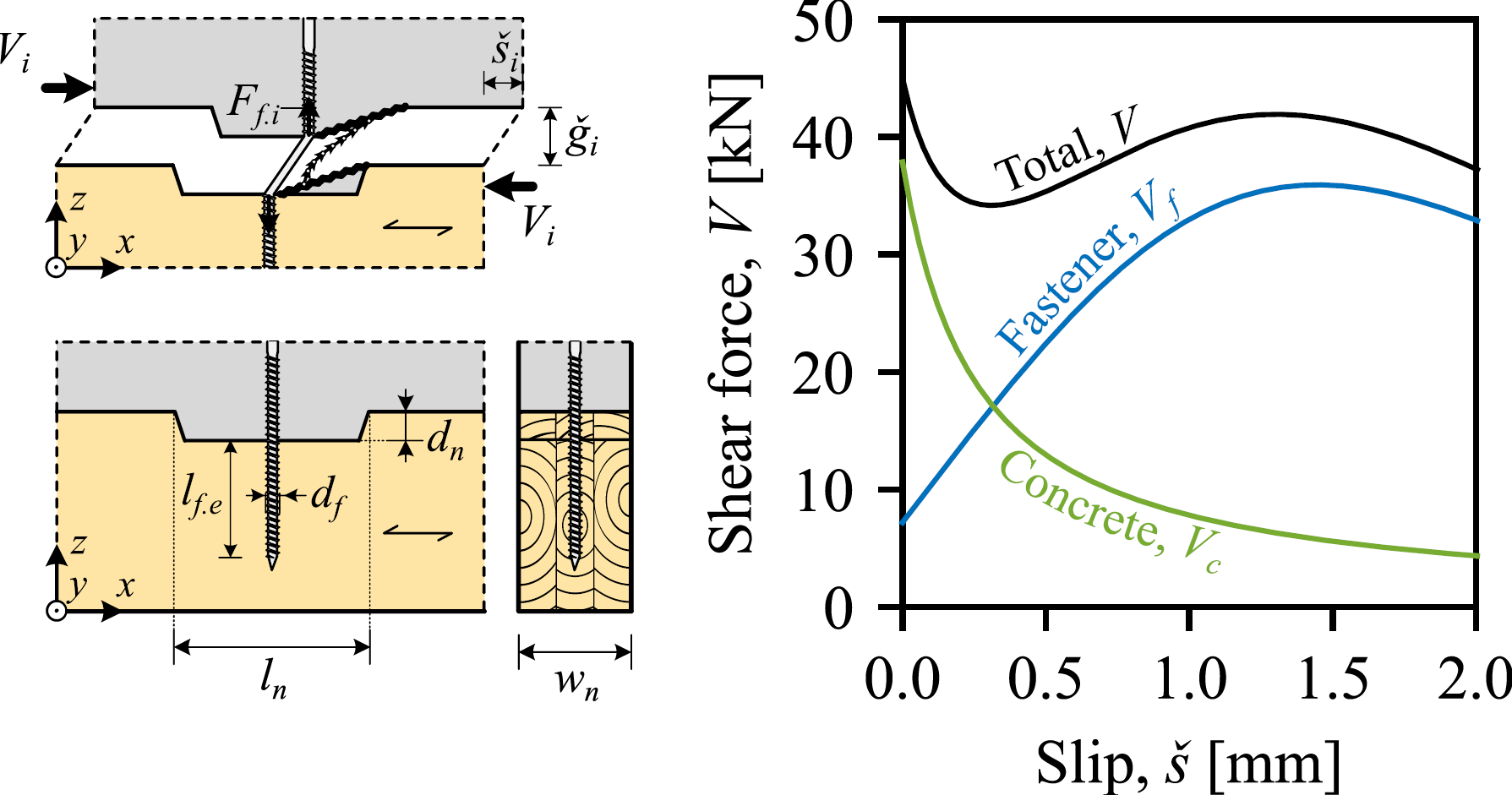
Peter Kolt Rasmussen (Technical University of Denmark/Ramboll [Industrial PhD Student]; co-authors: Linh Cao Hoang, Jesper Harrild Sørensen, and Bent Feddersen) presented a mechanically consistent model that represents a local concrete failure in timber-concrete composite (TCC) floors with notched connections. Based on the progressing deformation state of failure, the model accounts for the gradual softening of the effective concrete strength as well as the increasing activation of the fastener (see Figure 3). The approach can be used to design the fastener so that the notch is guaranteed to fail in a ductile manner, eliminating previous design restrictions and enabling the use of lower-strength (and lower-cement) concrete.
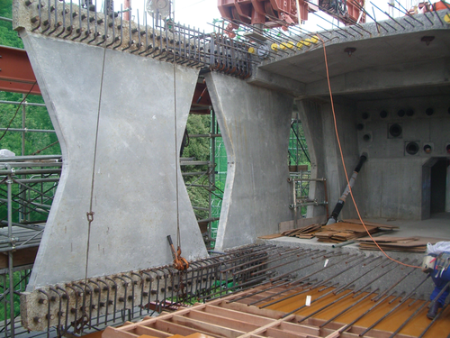
Dr. Akio Kasuga (The University of Tokyo / Sumitomo Mitsui Construction; keynote speaker) gave an impressive presentation on various projects with ultra-high performance concrete that he has been involved in as an engineer over the last 30 years. He had already realised small bridges with prestressed, non-metallic reinforcement (aramid) around 1990 – genuine pioneering work. I was furthermore impressed by the development of ‘butterfly webs’ with high-strength concrete and prestressed non-metallic reinforcement (see Figure 4). The first motorway bridge out of non-metallic reinforcement with these webs was completed in 2020.
I will certainly continue to follow these projects and look forward to the results and articles from them. My selection is not representative but only reflects my preferences. There were many other exciting projects at the conference.
Part 2 – Social aspects
Apart from the technical aspects, I will remember the following aspects from the conference in Budapest:
The discussions after the presentations were mainly very constructive and pleasant. I appreciated that. You could tell that the audience understood, for example, what it means to perform large-scale experiments. Accordingly, the inputs were always benevolent. During the breaks, it was easy to converse with other participants. It felt a bit like the very first week of university.
I got to know very friendly and excellent researchers with whom I will stay in contact. The discussions usually started with the research topic, then moved on to more general issues, such as employment conditions at universities or the working culture in the construction industry in different countries, and ended with private topics. I appreciated the exchange immensely.
Finally, I want to mention that I enjoyed spending this week in Budapest with Fabian Morger and Rebecca Ammann (both from kfmResearch group). We also very much appreciated Walter Kaufmann’s presence at the conference.
Part 3 – Conclusion
My conclusion is very positive. The conference broadened my research horizon, and I came back to Zurich very motivated. I really recommend attending the next fib PhD Symposium in Vienna in two years.
(Tip: If you book early, you travel – environmentally friendly and comfortable – from Zurich to Vienna by train in 1st class for less than 100 Euros).
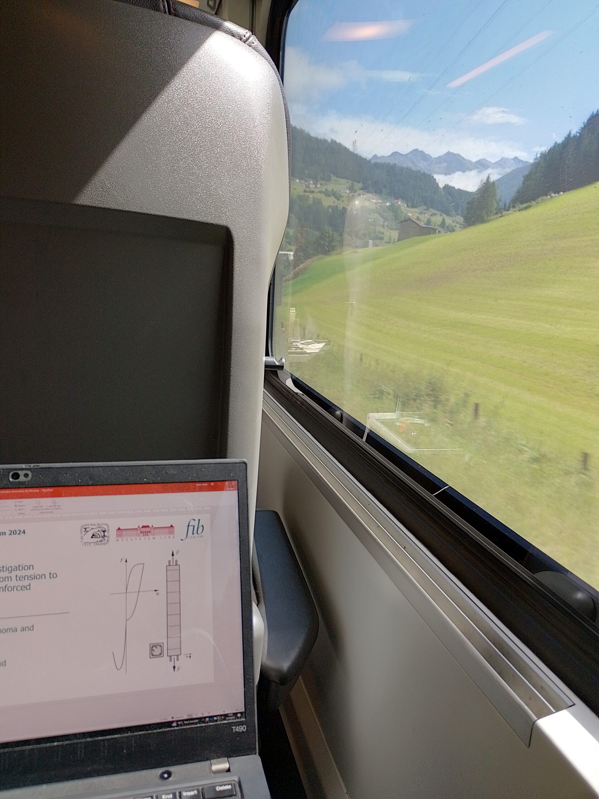
Simon Karrer
Link zur deutschen Version: Mit Entscheidungsbäumen Einblick in ein mechanisches Modell gewinnen
In this post, I would like to present how to use decision trees to gain insight into an existing model.
This blog already contains several posts on applications for artificial intelligence (AI) and, more specifically, machine learning (ML) in the civil engineering domain (AI-augmented Structural Engineering, AI-assisted strut-and-tie models, ML-enhanced finite element analysis and the use of neural networks within the direct stiffness method). In comparison, this post contains a much smaller, simpler application, intended for readers who do not have previous knowledge in machine learning yet.
One of the main advantages of decision trees is that they are fairly easy to implement with little coding experience and no machine learning experience. This makes them particularly suitable as an entry point into machine learning. Conjunctly, the results are easy to interpret as they can be graphically represented as an intuitively understandable tree. In this post, I will use this property of decision trees to gain a deeper understanding of an existing model, in the example a mechanical model that calculates the load-bearing capacity of a continuous slab strip.
Some background
Machine learning, a sub-field of artificial intelligence, encompasses several methods to describe and learn from large amounts of data. To counteract its most prevalent disadvantage of users being unable to comprehend how and why the ML algorithm reached a certain result (black box model), research in the engineering domain has been focusing on explainable AI. Explainable AI algorithms are those whose predictions can be judged for plausibility and accuracy or even retraced with domain knowledge. A comprehensive review of explainable AI can be found in this open-source paper.
One of the simplest and most explainable machine learning algorithms is the (classification) decision tree. It is an algorithm that learns to predict a value (often the answer “yes” or “no”) by successively partitioning the input data based on certain input parameters (the features). The decision process can be visualised as a tree, branching at each partition. Given that each partitioning step can be evaluated by the user, the model’s outcome is very explainable. Figure 1 shows the example of a decision tree that classifies numbers into the classes “prime number > 10” and “not a prime number > 10”, given the features of each number’s value and number of divisors. During training with the data set on the left, the algorithm finds the best partitions. The trained decision tree can then be used to predict the class of new samples. The Jupyter notebook with the code of this example can be found in this github repository.
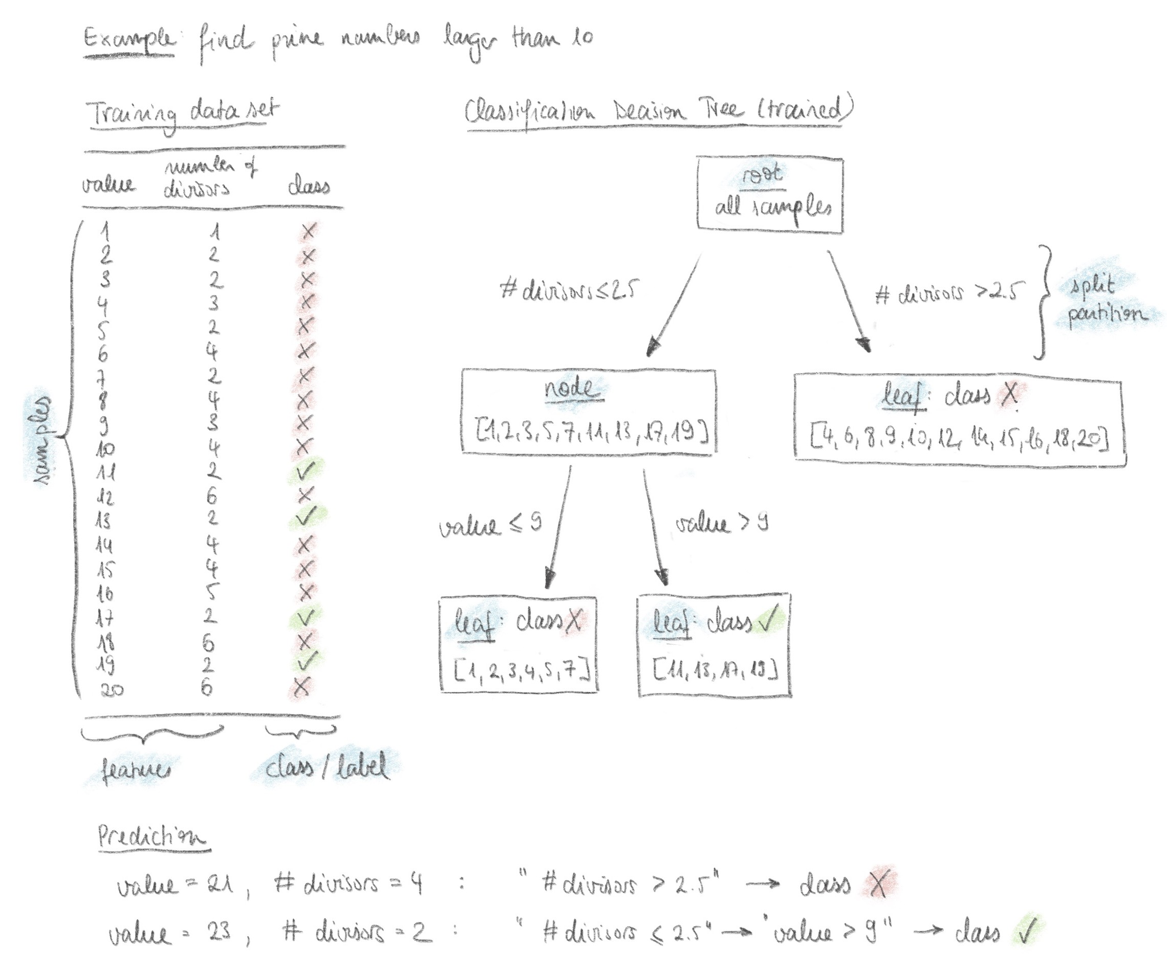
Application example
The following example demonstrates how to use a decision tree classifier to gain insight into an existing mechanical model. The focus is not, as usual and shown in the previous simple example, on finding the most accurate classification model to predict the class of new data, but on understanding which partitions the decision tree makes to reach the result. This can help gain insight into which parameters are most relevant for the outcome of the mechanical model.
Consider the example of a continuous reinforced concrete slab strip (Figure 2). An existing mechanical model, validated with large-scale experiments, calculates the non-linear response of the slab strip and can predict its ultimate load, taking into account the limited deformation capacity of the used materials. It is of interest to know which parameter combinations lead to a load-bearing capacity higher than the limit load calculated according to the Theory of Plasticity1It is possible to reach load-bearing capacities higher than the limit load with the mechanical model because it takes into account the hardening behaviour of the reinforcing steel, whereas the yield stress is used when calculating the limit load according to the Theory of Plasticity.. This means that in that configuration, the used materials have a deformation capacity high enough to use simplified calculation methods according to the Theory of Plasticity safely. More background on this topic can be found for example in this blog post.
The decision tree will be trained to predict a class of “ok” if the load-bearing capacity calculated by the non-linear mechanical model exceeds the limit load (Qu/Qpl > 1) or “not ok” otherwise.
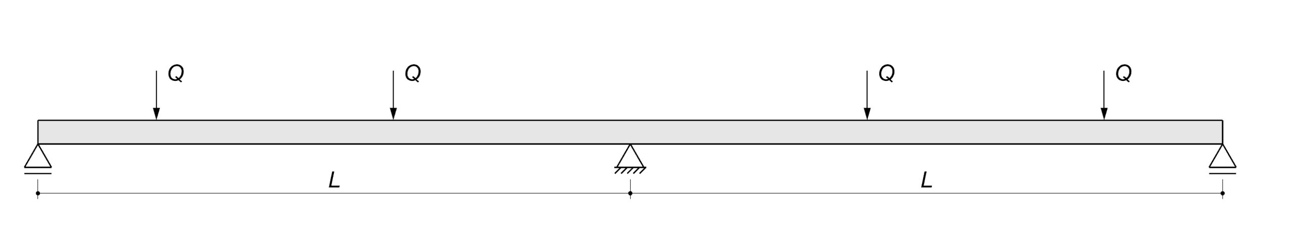
Creation of the data set
A data set can be generated by running the mechanical model many times with different input parameters. Choosing the correct parameters, or features in ML terminology, is one of the most crucial steps in data generation. The data set could look as follows:
| fs [MPa] | k [-] | εsu [-] | c [-] | ρs [%] | L [m] | fc [MPa] | Class |
|---|---|---|---|---|---|---|---|
| 496 | 1.09 | 0.087 | 0.11 | 0.78 | 4.37 | 54.1 | ok |
| 505 | 1.13 | 0.026 | 0.06 | 2.94 | 4.53 | 41.7 | not ok |
| 483 | 1.13 | 0.092 | 0.25 | 0.51 | 7.12 | 36.4 | ok |
| 517 | 1.07 | 0.082 | 0.08 | 0.88 | 4.37 | 57.8 | ok |
| 491 | 1.11 | 0.081 | 0.18 | 1.74 | 6.61 | 29.0 | not ok |
| … | … | … | … | … | … | … | … |
Notations
fs: Yield stress of the reinforcing bars
k: hardening ration of the reinforcing bars (k = fs/ft, where ft = tensile strength of the reinforcing bars)
εsu: strain at the tensile strength of the reinforcing bars
c: “roundness” of the constitutive material law of the reinforcing bars, see parameter c3 in “S. Haefliger, K. Thoma, and W. Kaufmann, ‘Influence of a triaxial stress state on the load-deformation behaviour of axisymmetrically corroded reinforcing bars’, Construction and Building Materials, vol. 407 (Link)
ρs: reinforcement ratio at the intermediate support (the reinforcement ratio in the span is calculated according to the linear elastic bending moment profile)
L: span width of the continuous beam
fc: compressive strength of the concrete
It is good practice to set the problem up such that the classes are balanced, i.e. an approximately equal number of samples per class, otherwise the algorithm is prone to favour the stronger classes.
Creation of the decision treeThe decision tree classifier can be created, using, for example, an implementation from the open-source Python library scikit-learn. Important parameters (called hyperparameters in machine learning) are the maximum depth of the tree and the minimum number of samples per leaf (end node). These hyperparameters help prevent overfitting of the data, as discussed later.
Training the decision tree
The training process starts at a root node containing the entire data set. The data is then partitioned using for example the Gini impurity criterion. For various possible features and split values, the algorithm calculates the Gini impurity to find the split that best minimizes impurity. This means identifying the feature and value that best separates the data into pure subsets. The algorithm creates a new level of nodes and continues on this level. This process is repeated until the maximum tree depth is reached or the number of samples in a node is too small to split further (i.e. the minimum number of values per leaf is reached). The performance of the decision tree is then evaluated to ensure its predictions are accurate enough for interpretation. This article provides an overview of methods for the performance evaluation.
Interpretation of the results
The most convenient way to interpret the results is by using a graphical representation of the tree, such as the function included in scikit-learn or dtreeviz. This is, of course, only possible up to a certain tree depth, after which is becomes unwieldy. Figure 3 shows an example of a tree with depth 3, though decision trees with different hyperparameters trained on the same data set were also analysed.
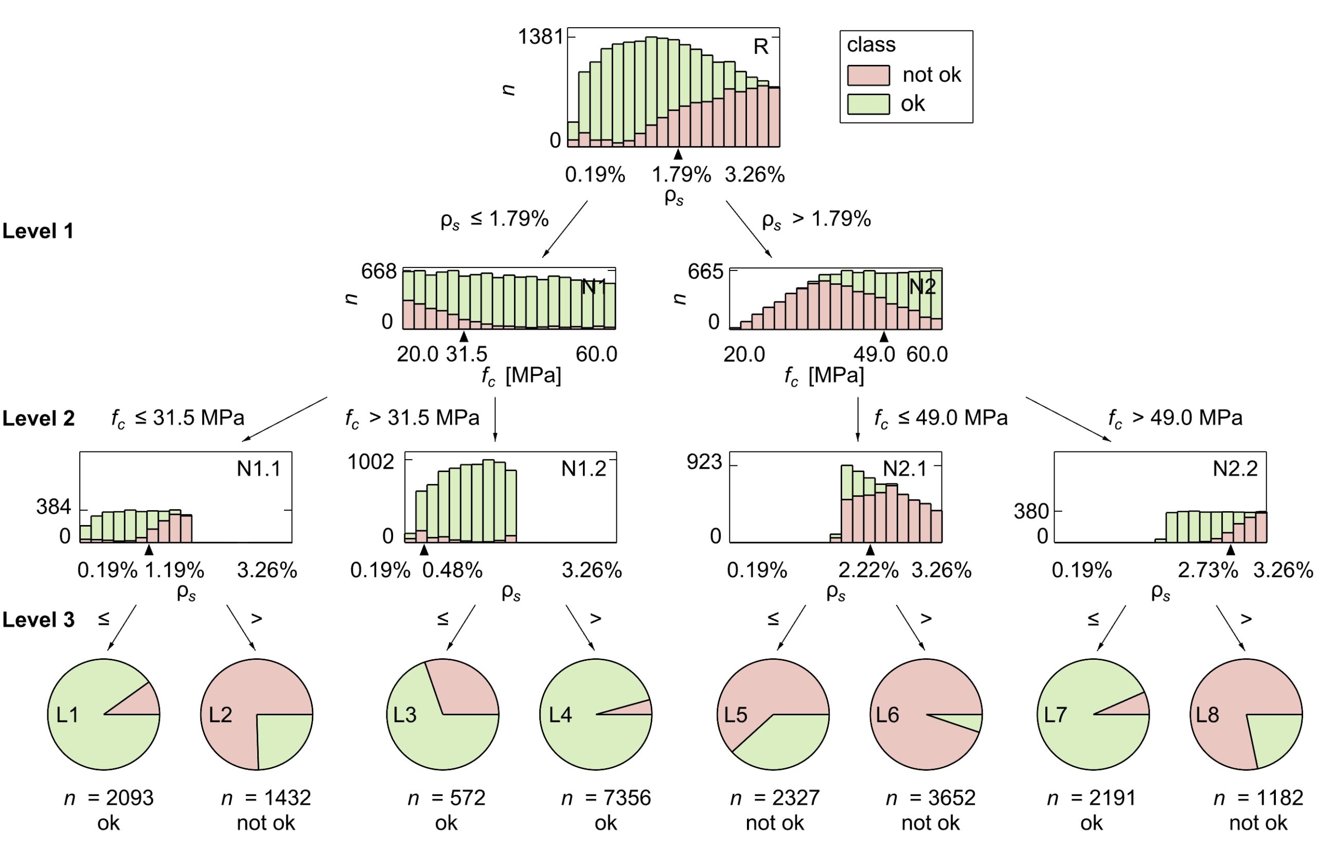
The partitions in the resulting tree can be interpreted with domain knowledge. In the application example, the first partition always (i.e. for all analysed tree depths) splits the data at a reinforcement ratio close to 1.8% (see Figure 3, Level 1). This indicates a meaningful relationship within the data.
Some background on the failure criteria in each section of the mechanical model helps interpret this relationship. The cross-section can fail either by rupture of the reinforcement or if the concrete in the compression zone reaches a nominal strain, set to indicate failure by concrete crushing. Following the graphical representation used in this blog post, it becomes clear that the algorithm separates the data according to the failure mode, see Figure 4. This is remarkable, considering the data contains no information on the failure mode (see Table 1) and speaks for its importance in the mechanical model.
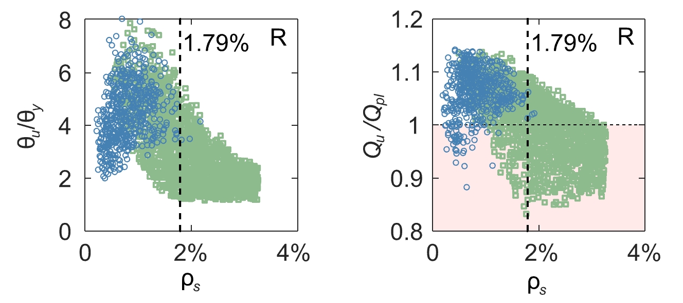
The second level of partitions is slightly less intuitive, as none of the failure criteria directly depend on the concrete compressive strength fc2Failure by steel rupture if the steel strain in any section exceeds the ultimate steel strain εsu. Failure by concrete crushing if the mean concrete strain at the compressed edge of the cross-section exceed 5‰, independently of the concrete compressive strength.. Plotting the data with the mechanical reinforcement ratio ω on the abscissa shows a clearer picture. The concrete compressive strength is part of the definition of the mechanical reinforcement ratio.
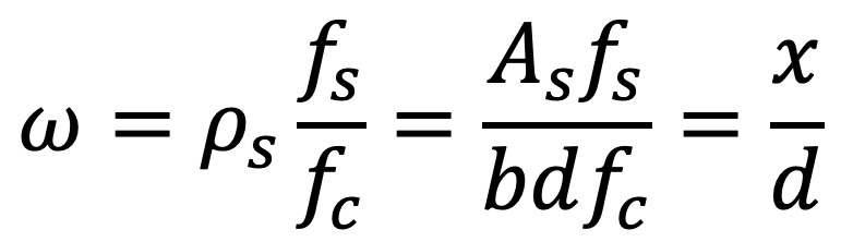
Notations
ω: mechanical reinforcement ratio
ρs: reinforcement ratio
fs: Yield stress of the reinforcing bars
fc: compressive strength of the concrete
As: Cross-sectional area of the reinforcing bars
b: width of the cross-section
d: static depth
x: distance to neutral axis / depth of the compression zone
This ratio is known to have a significant influence on the ductility of structures. It is included in the Swiss and European codes with the condition x/d < 0.35 that needs to be fulfilled in order to use plastic methods in design. Interpreting the partition from the mechanical point of view, a high concrete compressive strength reduces the depth of the compression zone x, favouring reinforcement rupture as a failure mechanism and large rotations at failure θu (i.e. high rotation capacity, high ductility).
A high concrete compressive strength fc keeps the ratio low, and the higher the reinforcement ratio ρs, the higher fc needs to be to counteract it. This may explain the different split values fc = 31.5 MPa and fc = 49.0 MPa at the branches of Level 2, see Figure 3 and Figure 5.
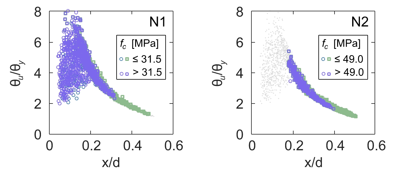
On Level 3 (see Figure 3 and Figure 6), the data is partitioned along the reinforcement ratio ρs again, solidifying the assumption that this is one of the most important design variables. Note that it is not usual for all nodes at the same level to be partitioned along the same variable. When interpreting the partitions, it is also important to consider their accuracy. In leaf L5, the decision tree misclassifies nearly 40 % of the samples, see Figure 3. Taking the accuracy into account, the interpretation of node N2.1 should be that samples with ρs > 2.22% are very likely “not ok”, but in the case of ρs < 2.22%, at least one additional level is required to separate the data well.
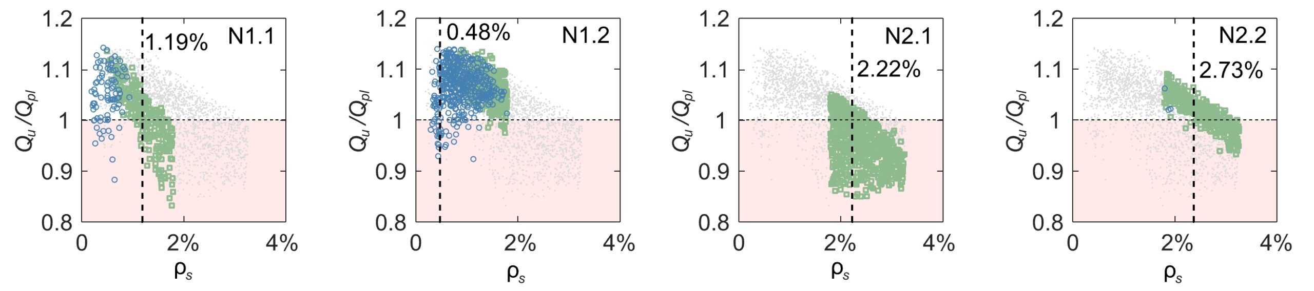
To summarize, creating a decision tree from data generated with the existing mechanical model and analysing the different partitions has (i) helped gain insight into what the most important features are and (ii) created an incentive to uncover the relation between these features and well-known mechanical principles.
Limitations of the method
As mentioned, the results are only easily interpretable up to a certain tree depth, limiting its applicability to very complex problems. The approach is only simple for (one) categorical questions with few answers, as seen in the application example. Furthermore, the fact that the decision tree can only split the data set along one design variable in each partition (see Figure 7 for an illustration in 2 dimensions) may limit its application to complex, non-linear problems with many dependent design variables.
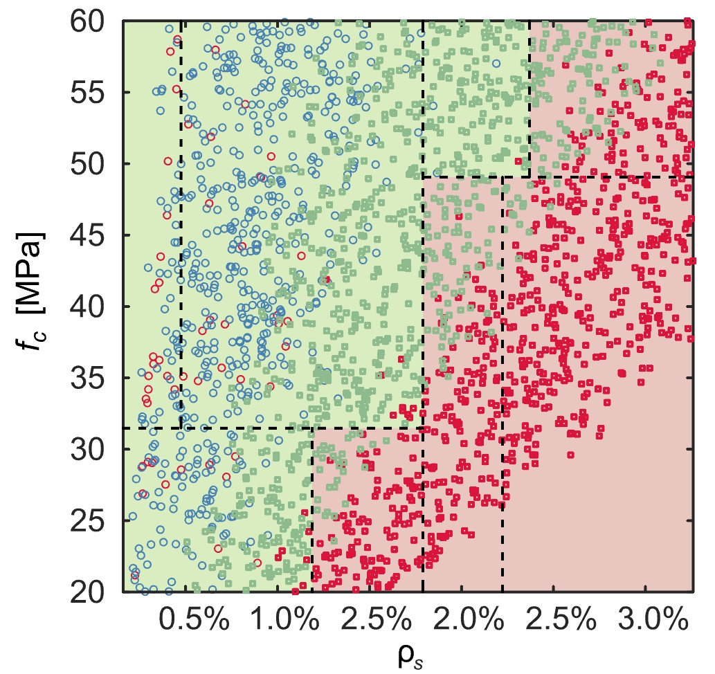
If the maximum tree depth is set too high or the minimum number of samples per split or per leaf are set to low, the decision tree might overfit, singling out certain points. This makes the fitted decision tree less generalisable and undermines the physical interpretability. A good way to check if the decision tree is overfitting is separating the data set into a training set and a test set. The decision tree is trained on the training data set without ever seeing the test data set. If the decision tree performs significantly worse when predicting the class of the test set compared to the training set, this is a good indication that it is overfitting. This article gives an overview of some methods to prevent or mitigate overfitting.
Decision trees rely on a balanced data set (i.e. with a similar number of samples per class), or they will favour the more represented class. This issue can be mitigated by introducing weighting factors, though they create an issue of their own, attributing overdue importance to outliers. If the weighting factor of the less represented class is five times the weighting factor of the more represented class, the tree could create a leaf with one outlier of the less represented class and four valid samples of the more represented class and still predict the less represented class in that leaf. This can only be noticed by carefully checking the plausibility of the partitions leading to each leaf. It is thus preferable to create balanced data sets or, if possible, remove outliers before training the decision tree.
Like all ML models, the outcome of decision trees depends heavily on the data. One should be aware that small changes in the data or the hyperparameters can lead to a different tree. As decision trees can be trained quickly, it is recommended to vary the hyperparameters and check that the trees and their interpretation remain similar.
If the decision tree is not accurate enough, one could instead use a random forest algorithm, which generates multiple decision trees during training and provide the majority decision of these trees for a given dataset and given hyperparameters. It can represent complex data sets more accurately and is more robust against overfitting (see this article for a comparison). However, this comes at the cost of explainability as the large number of generated decision trees makes it impractical to manually interpret them all. With random forests, it is thus more convenient to use the relative importance of the features for interpretation, see Figure 8.
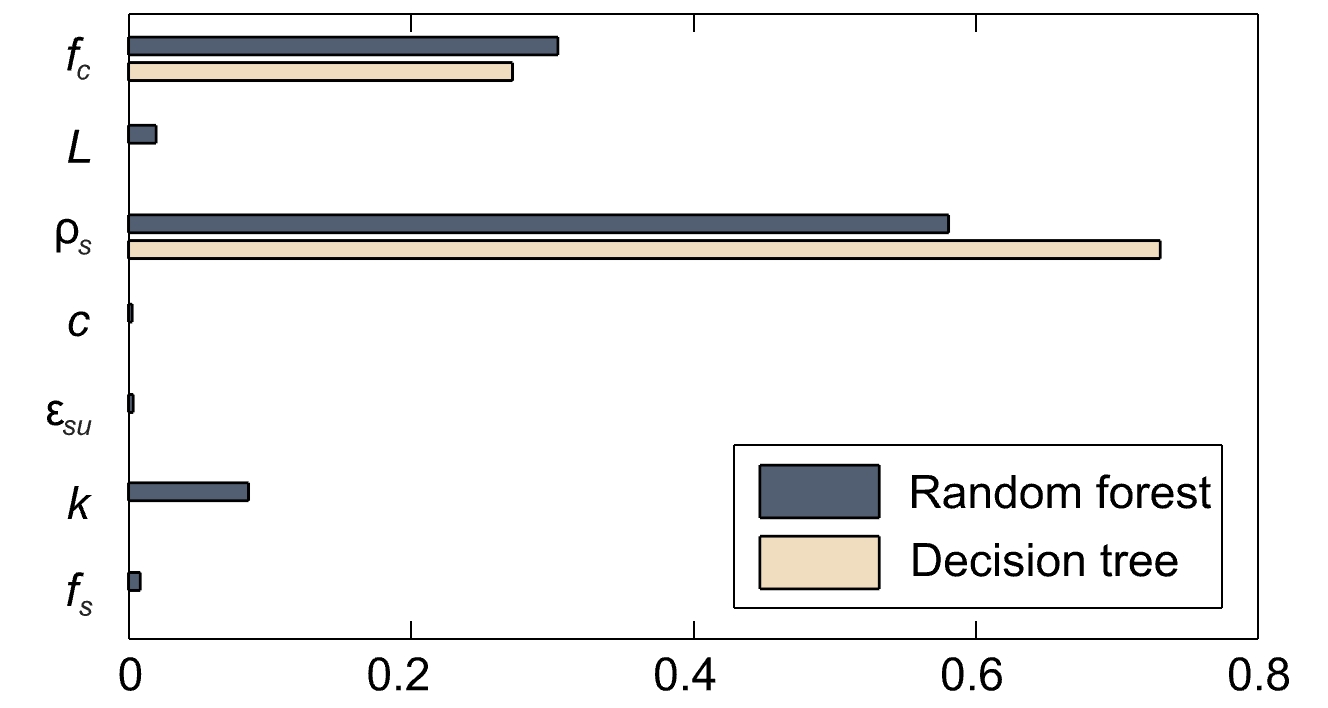
Personal assessment
Despite the limitations, I think using a decision tree on data generated by an existing model is an interesting approach because one can get a better understanding of the model and the data with little effort. The process helped me avoid getting overwhelmed by the high dimensionality (many features) in the mechanical model since the decision tree gave some indications on which ones to focus on. It also had the benefit of sparking my creativity and making me think about the problem differently when the results did not immediately align with my expectations. This led me to delve deeper into my preliminary theoretical knowledge of the problem and ultimately to a deeper understanding of the mechanical model.
Resources
This github repository contains a short guide to get started with decision trees (using the sklearn toolbox and Visual Studio Code) and the Jupyter notebook with the code for the decision tree example in Figure 1 (prime numbers).
Nathalie Reckinger
Link zur deutschen Version: Einblick in die Deep Neural Network Direkt Stiffness Methode (DNN-DSM)
This blog post describes the most important steps that were done throughout the development of the deep neural network direct stiffness method (DNN-DSM). The overall conceptual method derivation is basically separated into three parts: (i) the finite element simulation and development of appropriate data sets, based on local shell-element simulations, covering for instabilities at the cross-sectional level; (ii) the development of deep neural networks, suitable to predict the individual tangent stiffnesses; (iii) the implementation into the direct stiffness method.
The developed deep neural network (DNN) models were trained on data sets derived from a pool of numerical LBA (linear buckling analysis) and GMNIA (geometrically and materially nonlinear analysis with imperfections) shell FE-simulations, designed in such a way that only local buckling is the main instability phenomena for the investigated rectangular and squared (RHS and SHS) cross-sections, see Figure 1.
The main verification work against experimental tests goes back on the Hollosstab project (Link). The derived FE-models were partially adapted based on this investigation and were further developed to match the conditions for local buckling. The developed FE-models are described as follows; (i) Abaqus Type S4R elements, with a mesh density of around 60 elements in circumferential and 50 – 100 elements per meter in longitudinal direction; (ii) Geometry based on code provisions of EN 10210-2:2006 and EN 10219-2:2006, with a length L set as the bigger value of the width W or the height H ; (iii) Deformations applied through defined reference points located at the upper and lower edge of the cross-section, connected through multiple point constraints (MPC-Pin formulation); (iv) Non-linear material models for hot-rolled (bilinear + non-linear model) and cold-formed steel (two-stage Ramberg Osgood model); (v) LBA analysis carried out to identify elastic critical buckling resistance and the eigenshape (local imperfections); (vi) GMNIA simulation performed to determine the realistic buckling resistance.
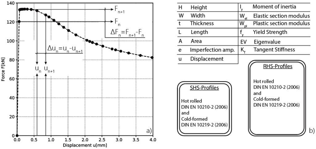
526 European hot rolled and cold-formed RHS and SHS profiles, three different steel grades ranging from mild to high-strength (S355, S460 and S700), as well as three different local imperfection amplitudes (B/200, B/300 and B/400; where B is the smaller dimension of either the profile height or width were taken into account. In sum, 9468 GMNIA simulations were run to create the basis for data extraction.
Therefore, the LBA analysis output from Abaqus was used to extract the cross-section-dependent elastic critical buckling load. The GMNIA analysis results, on the other hand, were used to determine the incremental deformation and rotation steps and an associated differential force and moments, see Figure 2 a) for compression. These values were subsequently used to calculate the incremental tangent stiffness values on which the DNN models were trained.
A total of 193 individual hyperparameter combinations for different DNN models were tested within the framework of preliminary investigations using the Random Search Method. This workflow was suitable in order to detect the overall tendencies within the DNN architecture. All calculations were performed on the basis of a train and test philosophy, meaning that a specific data amount was used for the training (80%) and an additional independent amount for the validation process (20%). The subsequent DNN model was built with four hidden layers (27, 27, 18, and 9 neurons), each ending with a ReLU activation function, a learning rate of 0.0005, and the Adam optimizer.

The general implementation of the DNN-DSM is based on the generic definition of the DSM for beam elements.
![]()
The DNN-DSM makes use of this implementation to predict a local nonlinear tangent stiffness matrix according to given nodal deformations or rotations. The neural network takes some of the features from Figure 2 b), as well as an absolute deformation or rotation at every step (see Figure 3 a) for compression and b) for bending) to predict a local nonlinear tangent stiffness matrix, as proposed through following equation.
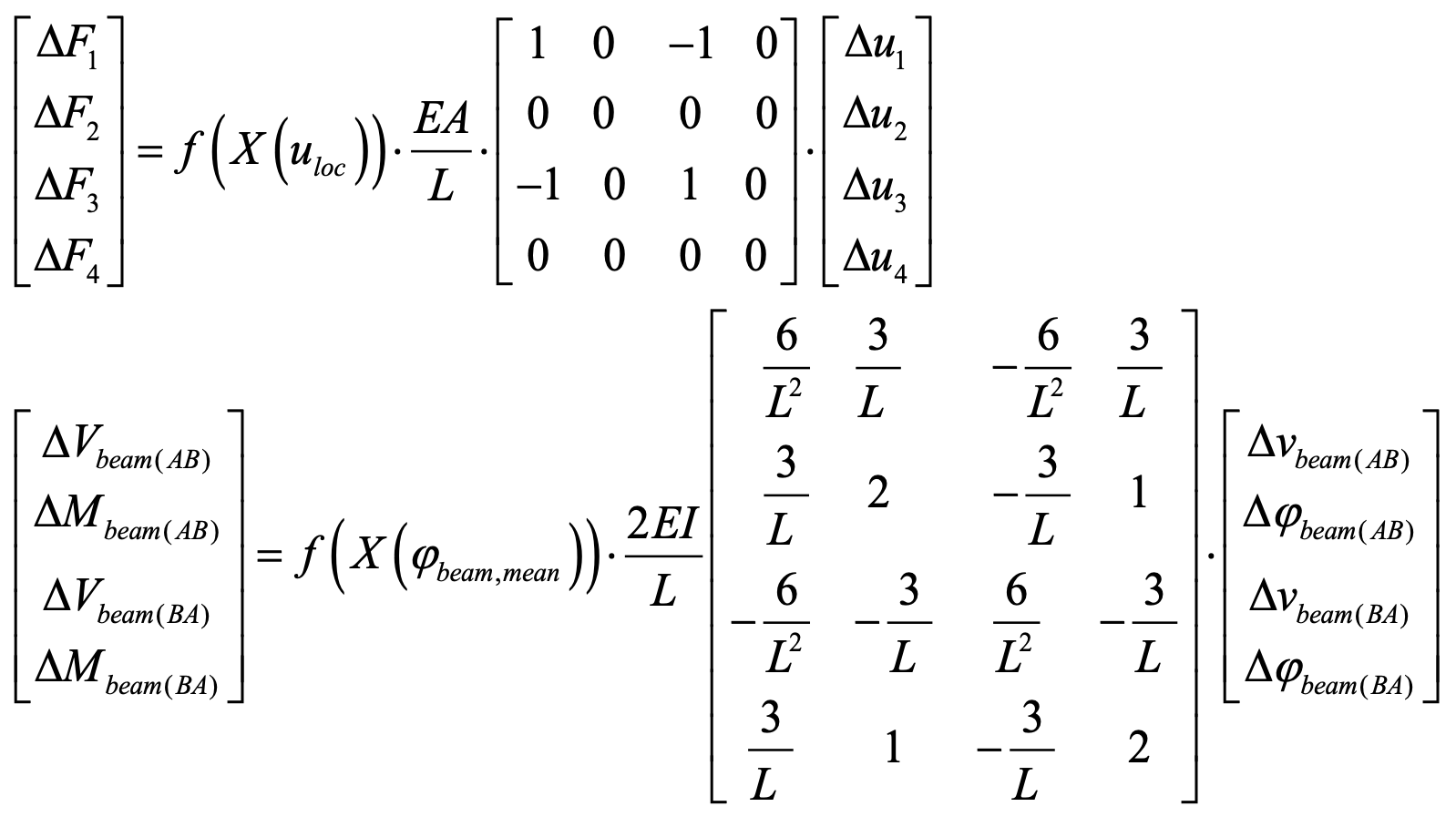
Implementing the beam element differs slightly from implementing the truss element by modifying the beam stiffness matrix according to a given mean rotation φ. The corresponding definition of the rotation φ for an element is stated in Figure 3 b). Therefore, an equal constant rotation at both ends is assumed, which is accurate enough as long as the element length remains small.
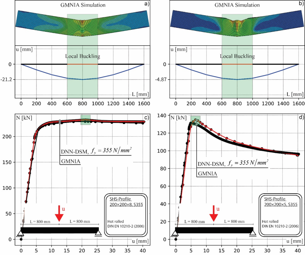
Three-point bending results are presented in Figure 4 for two hot-rolled profiles, SHS200x8 (S355) and SHS200x5 (S355). Figure 4 a) and b) show the output deformations from Abaqus and the corresponding DNN-DSM predictions. Both Abaqus models form a local buckle around the load introduction area. The DNN-DSM replication uses only 8 elements with 2 dofs at each node (vertical displacement and rotation), leading to a total of 18 dofs for the whole system. Note that the Abaqus model uses 77298 dofs, in order to calculate the non-linear load-deformation curves from Figure 4 c) and d). A very close result can be recalculated with the DNN-DSM approach. The elements around the load introduction area reach their maximum cross-section-dependent capacity and fall into post-buckling, which leads to the overall drop of the loads. Deviations of maximum forces are below 3% for this particular case. However, corresponding deformations deviate stronger from each other. In the case of the SHS200×5 profile, the DNN-DSM approach lies 30% above the GMNIA shell FE results. This might be drawn back on effects not included in the DNN-DSM, like local crushing in the load introduction area or a slightly smaller local hinge area that could affect the overall behavior. Nevertheless, the overall system behavior was replicated successfully with the DNN-DSM, predicting the pre- and post-buckling range in less computational time compared to the Abaqus simulations. The DNN-DSM algorithm was finished after approximately 150 sec, the Abaqus calculation after around 240 sec, for the case of three-point bending. This time includes only the actual calculation. Taking into account the modeling effort would lead to significantly bigger differences.
Summing up, this post highlights some selected insights into the development and application of the DNN-DSM method, a novel approach that couples beam FE with deep neural network models to mimic the local buckling failure of advanced FE-shell simulation. Apart from data development, data-set generation and method implementation, a comparison between the DNN-DSM and Abaqus GMNIA was presented to showcase capabilities in the prediction of the full load-deformation path, as well as model size reduction potential and corresponding time savings. More detailed explanations with additional background information can be found under the following publication (Link, [1]).
Andreas Müller
Literature
| [1] | Müller, A. Advanced Inelastic Analysis and Design of High Strength Steel Structures with Machine-Learning-Derived Predictive Methods. Doctoral Thesis (2023). ETH Zürich. |
Link zur deutschen Version: Über die Verwendung von Hochleistungsfaserbeton im Brückenbau.
This post highlights the outcomes of an ongoing collaborative research project between the Universidad Politécnica de Madrid (UPM) and ACCIONA’s Construction Technology Centre, aimed at investigating the application of High-Performance Fibre Reinforced Concrete (HPFRC) in infrastructure construction. The project adopts a comprehensive approach, encompassing conceptual analysis, material development, and experimental testing. The leading UPM team is composed by Rafael Ruiz, Hugo Corres, and Leonardo Todisco. Leonardo, during this semester, is serving as a visiting professor at the ETH Zürich’s Chair of Concrete Structures and Bridge Design.
HPFRC has a compressive strength of approximately 100-120 MPa, enabling elevated prestressing levels compared to conventional concrete. This potential facilitates significant reductions in concrete volume and fosters the realisation of larger spans made in precast concrete bridges. In addition, the shear strength contributions provided by steel fibres and prestress allow to replace the conventional shear reinforcement, which represents around 40% of the mild reinforcement steel in conventional girder bridges. The research findings indicate that a fibre content of around 80 kg/m3 (Vf ≈ 1%) is sufficient to ensure adequate ductility when stirrups are removed. Additionally, the quick strength development of the cementitious matrix allows the early transmission of prestressing force, accelerating the manufacturing process. This high early-age strength is linked to a quicker development of rheological deformations, thereby reducing long-term effects, as delayed prestress losses. Finally, these mechanical performances are complemented by a notable enhancement in durability properties compared to conventional concrete.
The developed HPFRC mix, comprising 500 kg/m3 of cement, 50 kg/m3 of silica fume, and 80 kg/m3 of 4d-60 mm length steel fibres, offers promising mechanical characteristics at a cost approximately 2.5-3.0 times that of conventional concrete, significantly lower than an Ultra-High-Performance Fibre Reinforced Concrete. The developed HPFRC exhibits a compressive class C120, post-cracking bending class of 13a, and spreading class F5.
The developed HPFRC has been applied to the design of a U-shaped girder for roadway bridges (link).
The bridge superstructure comprises two U-shaped girders, each made with three 20-meters-long precast segments, resulting in a total span of 60 meters. The bridge superstructure is completed by a deck made of conventional concrete. Its cross section and 3D representation are shown in Figure 1. The prestressing is located outside the concrete, within the U girder, leading to a strong reduction of the webs and bottom slab thickness. Also, some tendons deviate at L/5 from the supports for a better approximation to the bending moment distribution.
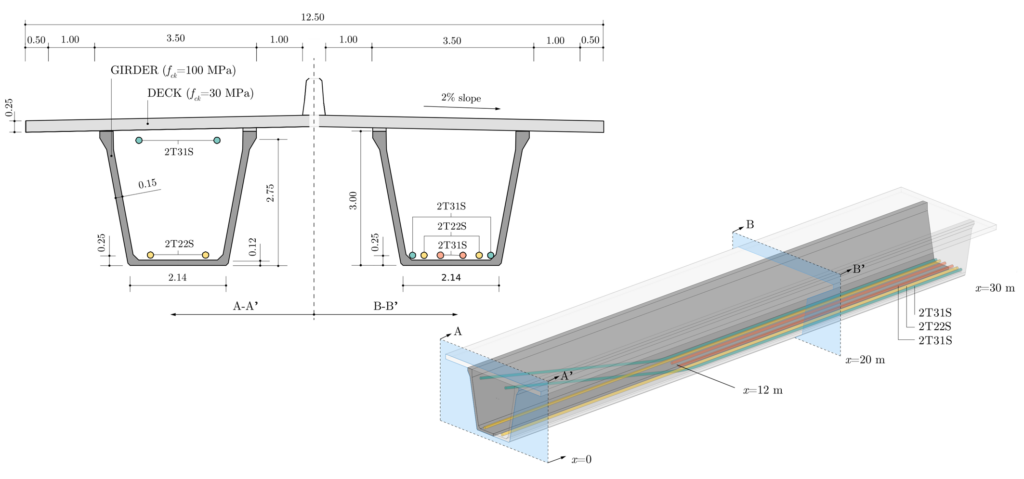
When compared with other reference projects with similar geometric features and conventional materials, the concrete consumption is reduced by 50%, the mild reinforcement is reduced by 67% and the prestressing steel increases by 17%. Overall, the HPFRC solution achieves a 14% reduction in cost, notwithstanding additional benefits such as reduced self-weight and increased durability.
To address concerns regarding cold joints between pourings and fibre orientation, two rectangular-shaped panels (Figure 2, left) were cast in 4 layers, compacted by a poker vibrator. Prismatic samples with variable orientation were extracted and the EN 14651 results (Figure 2, right) were considered satisfactory with no discernible effects attributable to fibre orientation or discontinuity planes (link).
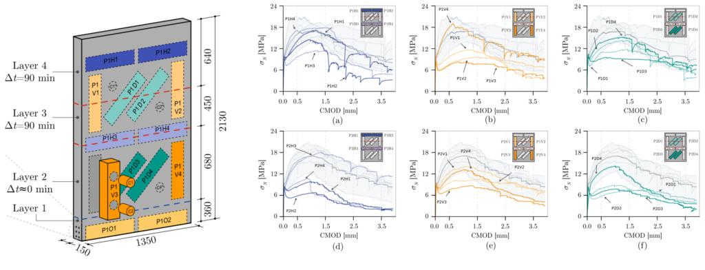
However, the shear response of such elements is still under scientific discussion and most design models provide scattered and highly conservative predictions (link), discouraging the use of HPFRC. Consequently, an experimental investigation on eight full-scale HPFRC beams was carried out (Figure 3). The beams were tested with different levels of prestressing and were instrumented with refined optical digital image correlation (DIC) measurements.
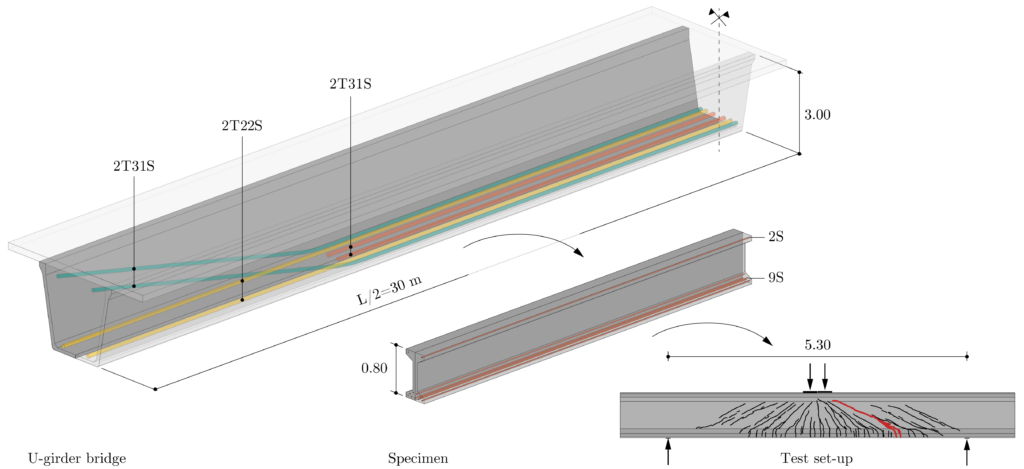
Using the experimental data, crack development and DIC-based kinematics were investigated in detail, as well as the associated contributions of potential shear-transfer actions (link). The results (Figure 4) revealed a significant contribution of the fibres, as well as of the inclination of the compression chord for high levels of prestressing, while the other potential shear contributions (i.e. aggregate interlock, dowel action) were negligible.
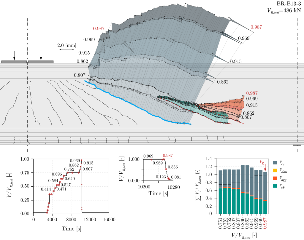
In conclusion, the study provided valuable insights into the application of HPFRC in infrastructure construction, highlighting its potential to change traditional bridge design. A 60 m-span girder bridge made of HPFRC was identified as a cost-competitive (-14% in cost) alternative to conventional solutions. It is composed of three precast segments prestressed by unbonded tendons, without the need for conventional shear reinforcement, thanks to the prestress and fibre’s contribution to shear strength. Ongoing efforts are focused on refining shear design models to better account for the unique properties of HPFRC and facilitate its widespread adoption in the industry.
Leonardo Todisco
Link zur deutschen Version: Eine neue Kombination aus Maschinellem Lernen und der Finiten-Elemente-Analyse.
Many of the previous blog posts have already emphasised the importance of sustainability in the design of concrete structures (Blog Rebecca Ammann, Blog Sophia Kuhn). This blog post presents a different method towards finding design methods that allow for a more efficient design or verification of reinforced concrete structures to reduce the concrete consumption and thus build more sustainably.
Current design tools for reinforced concrete (RC) structures mostly rely on linear elastic finite element analyses (LFEA). They approximate the strongly nonlinear material behaviour of RC with linear models and tend to be overly conservative (Thoma et al. 2014). Such an approximation can hence lead to economically as well as environmentally inefficient designs of RC structures.
On the other hand, several different models for non-linear finite element analyses (NLFEA) exist, which comprise different methodological approaches. One example is the implementation of the mechanically consistent Cracked Membrane Model (CMM, Kaufmann and Marti 1998, Thoma et al. 2014). This method can reproduce the real behaviour of RC structures more accurately compared to LFEA and can be applied universally, also for discontinuous structures (see also previous blog by Marius Weber). However, NLFEA simulations are rarely carried out in practise due to their computational inefficiency and their complex dependency on multiple uncertain (material) parameters. More than one non-linear calculation is rarely executed, making it difficult to investigate different design or verification scenarios or even to optimise a RC structure.
In contrast, novel digital processes, such as machine and deep learning (ML/DL) systems as well as differentiable simulation are the current state-of-the-art for differentiable modelling and gradient-based optimisation. It has been shown that ML and DL can discover patterns and generalise well from data (LeCun et al. 2015, Shen et al. 2023). Once they are trained, they are fast in predicting desired performances. Recent advances in physics-based machine learning (PBML) have shown the potential of ML methods in combination with conventional computational physics models over various domains, such as in fluid dynamics, solid mechanics as well as structural mechanics. Physics-informed neural networks (PINNs, Raissi et al. 2019) are one example of this type of machine learning, where compared to standard neural networks (NN), the underlying physical equation such as a differential equation is incorporated directly in the loss term of the neural network. Figure 1 shows an example of such a PINN for an RC beam, according to the Euler-Bernoulli beam equation. The PINN only requires the locations x at which the differential equation should be evaluated as input data. Once trained, it can predict the vertical deformations (w) and bending moments (M) of a simply supported beam given the location x along the beam for a given set of geometry, material parameters and loading.
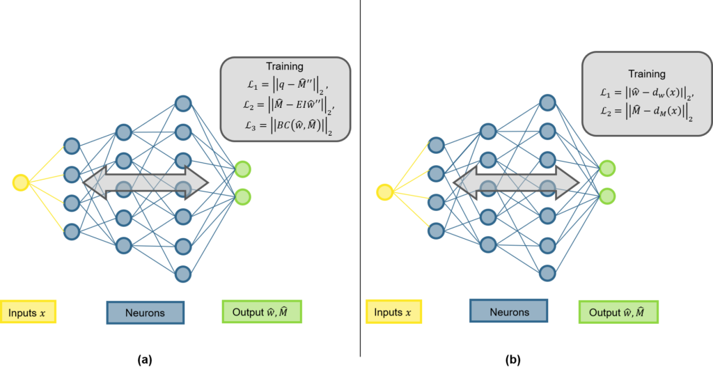
For the application of novel ML / DL methods in the construction sector, a crucial point is to include domain knowledge (e.g. the differential equation of the Euler-Bernoulli beam) in the ML systems, as can be done with PINNs, and ensure validity as well as acceptance with reliability assessments familiar to engineers. In addition, the construction sector is not a domain where typically a lot of data is available to train ML models on, which is why incorporating physics-based methods would be beneficial. Even though the emerging novel PBML methodologies show promising results, most of these methods fail to generalise outside of the parameter space they are trained on, restricting the application possibilities to problems far from real-world applications. Hence, we intend to develop a novel mechanics-based machine learning methodology for efficient modelling of RC elements. This novel methodology shall be developed by combining ML with traditional FEA approaches, with the main objectives shown in Figure 2: The method should be developed on a structural element level, i.e. for individual beams, plates or shells and has the goal of increasing the efficiency of the current methodology. This shall be reached by developing interpretable, mechanics-based methods in the current framework of FEA and optimally implementing it in a standard FEA software for practicability.
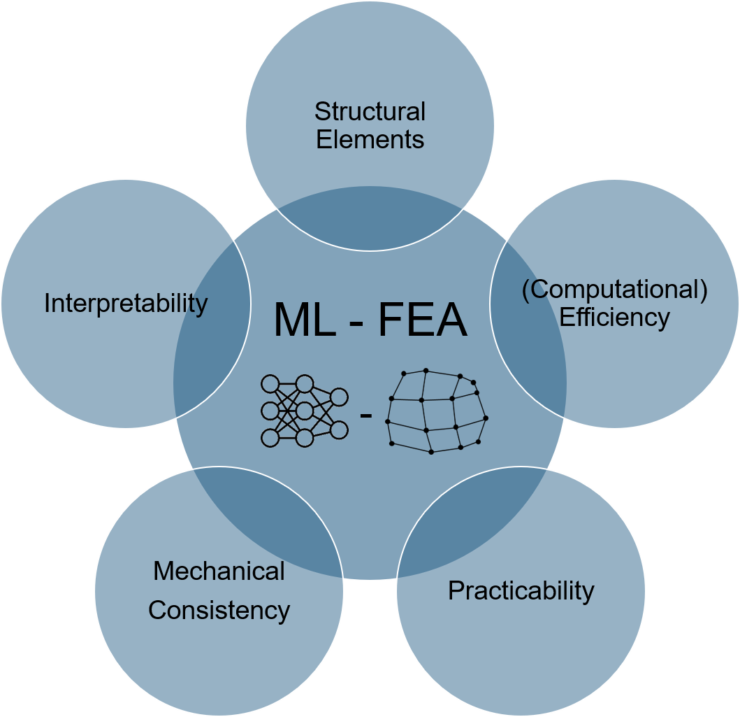
To exemplify the methodology, a preliminary study was carried out, investigating a simplified NLFEA of a beam element. Figure 3 shows the workflow of this simplified NLFEA, where the simply supported beam is first divided into finite beam elements, which are analysed at the cross-section level to determine the local and then global stiffness matrix to finally evaluate the global equilibrium. The goal was then to replace the highly iterative and time-consuming calculation at the cross-section level in the analysis with a standard NN (see Figure 3). This NN is trained with data from parametrised simulations of moment-curvature graphs. The parametrisation includes variations of material strengths and stiffnesses, height and width of the finite element, etc. In the end, the NN receives the moment at the finite element as an input and predicts curvatures and corresponding tangent stiffnesses of the cross-section (EI). By replacing this calculation step with a NN, a surrogate finite element is created which doesn’t require iterations on the cross-section level. This finite element can be used for any type of structure, which can be modelled with RC beam elements, hence allowing for larger generalisability. The next steps are now to translate these findings to shell structures and incorporate physics in the NN as explained above. Ultimately the developed ML-FEA method will be compared with state-of-the-art NLFEA software.
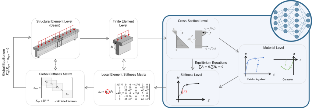
In conclusion, with this combination of ML methodologies and FEA we hope to create a tool which will allow for more detailed design or verification of existing structures and in this manner help utilising RC more efficiently. If you are interested in this topic, stay tuned and we will be glad to tell you about the developments of this project as soon as possible.
Vera Balmer
Link zur deutschen Version: Ein erster Schritt in Richtung KI-gestützte Fachwerkmodellgenerierung.
Strut-and-tie models are a widely applied approach to the design of reinforced concrete structures loaded in-plane such as beams or walls, at the level of approximation I. They are particularly suitable for geometric or load discontinuities. With the truss analogy, the force flow is shown with the struts representing concrete in compression and the ties representing reinforcement in tension. The classical stress field approach provides a more detailed design approach at the level of approximation II, which treats the force flow more continuously. A suitable stress field can be derived from a strut-and-tie model by considering nodal regions1Further extensions of the classical stress field approach might include elastic-plastic or non-linear constitutive laws and are often implemented in finite element models, such as the compatible stress field method, which is particularly suitable for existing structures.. Strut-and-tie models and stress fields are lower bound (static) solutions according to the theory of plasticity. Therefore, it is worth exploring different solutions during the design stage to obtain the closest one to the complete solution and to maximise the applicable load. They can also be used as plausibility checks for finite element analysis results to avoid modelling errors. However, the selection or suggestion of suitable strut-and-tie models is highly dependent on the expertise and experience of the design engineer and is a time-consuming and iterative process2For a more historical perspective on the development of truss models, please read this blog post.. This hinders the widespread use of strut-and-tie models that provide an interpretable and safe design. Digital tools such as machine learning could be used to bridge this gap. They could assist in achieving more consistent designs for reinforced concrete structures between different engineers and could ultimately be used for quality control and to reduce material usage. As a first step towards this goal, this article presents different attempts and their limitations of automated strut-and-tie model suggestions, followed by the research question and how a tool to validate strut-and-tie models with their corresponding stress fields helps to achieve our research goal.
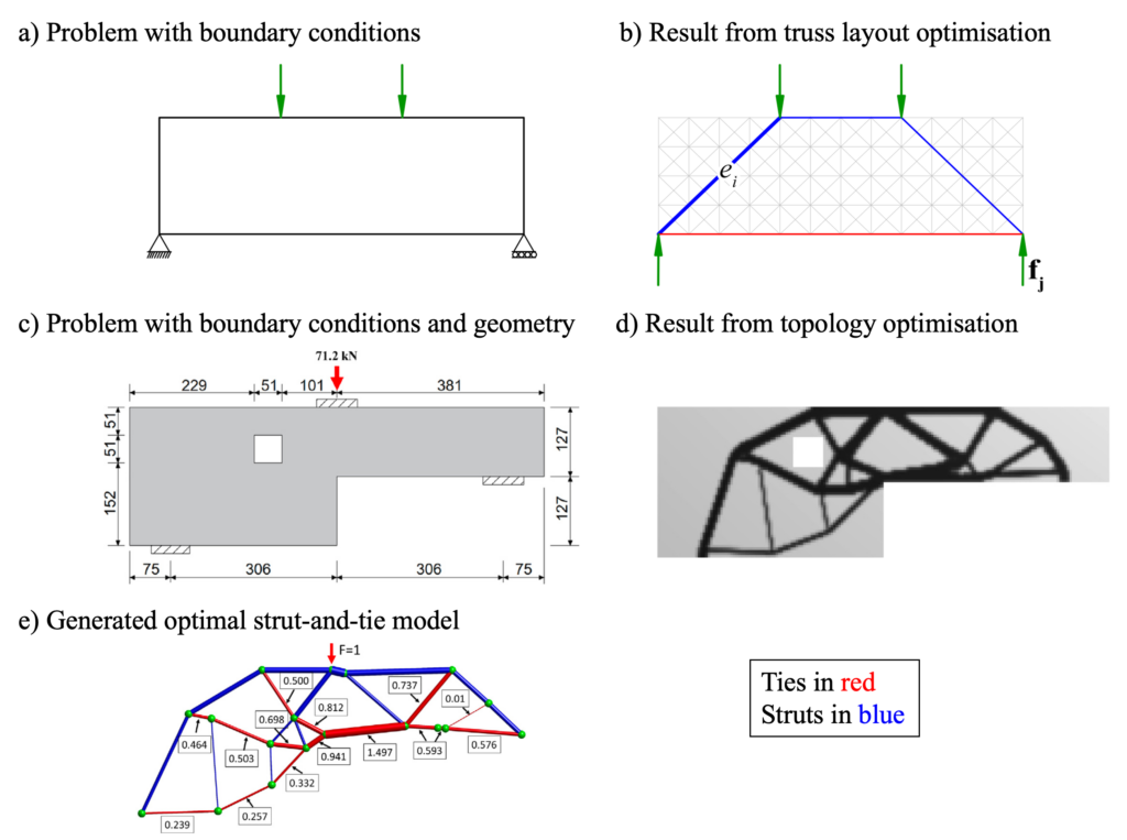
Various approaches have been developed for automated strut-and-tie model suggestion tools, primarily based on optimisation. The majority of these approaches can be categorised into two main groups: discrete (layout) optimisation and continuous optimisation. Discrete (layout) optimisation schemes, also known as truss layout optimisation, are based on a predefined grid or layout representing all possible nodes and edges of the resulting truss (see Figures 1a-b). Mathematical optimisation algorithms are applied to minimise a specific objective function, such as the total volume of reinforcing steel, within predefined constraints. This approach results in a regular pattern and it offers the flexibility to penalise inclined reinforcement to obtain a truss with only orthogonal reinforcement but still allow for inclined struts.
In contrast, continuous optimisation techniques often rely on topology optimisation. Topology optimisation typically aims to minimise the overall weight or volume of a structure through material removal while adhering to specific structural constraints, such as stress limits or deformations (see Figures 1c-d). It demands a high degree of geometric freedom and usually provides solutions based on linear elastic isotropic material behaviour, which speeds up the computations considerably. However, in the case of structural concrete, this simplification may not accurately represent the true material behaviour, as it neglects the influence of the reinforcement orientation, cracking, the different behaviour of reinforced concrete under tension and compression, and further material nonlinearities. Topology optimisation yields an intermediate result and is not yet the final strut-and-tie model (Figure 1d) with specific node locations and edges. Finding a suitable truss is difficult as one has to balance the constructability aspects (e.g., avoiding inclined reinforcement, or considering anchoring of the reinforcement) with the structural and material efficiency (Figure 1e).
To conclude, the discrete optimisation approach is often too rigid to capture complex geometries and offers little flexibility for user adjustments, while the continuous approach struggles to account for constructability aspects such as accommodating inclined reinforcement or very short ties. In addition, the issue of multiple load cases has been scarcely studied where for each load case a new strut-and-tie model needs to be defined. These challenges have led to a gap in the current strut-and-tie model generation methods. Few software applications have incorporated these optimisation-based approaches and they have not yet gained widespread adoption in practice. Moreover, the use of optimisation results in a single strut-and-tie model. However, the engineer needs design flexibility to consider other aspects unique to their structural problem and expertise, and the possibility to influence the resulting strut-and-tie model, as they remain the design maker at the end of the day. We want to address this research question in a data-driven but also domain-specific manner using machine learning tools by developing an AI-assisted automated strut-and-tie model generation tool. This tool does not solely focus on generating the most optimal strut-and-tie model but instead suggests a range of suitable strut-and-tie models and therefore also allows for an interplay between the user and the machine to assist the engineer in the decision-making process.
As a first step towards this goal and for a reliable data generation pipeline, we need a validation tool to verify the proposed strut-and-tie models. The pipeline is needed to train and test the final machine learning model, and validate the final suggestions. Focusing on the ultimate limit state, this tool does not only check force equilibrium but also the stress fields and their nodal regions to achieve a more refined design at the level of approximation II.
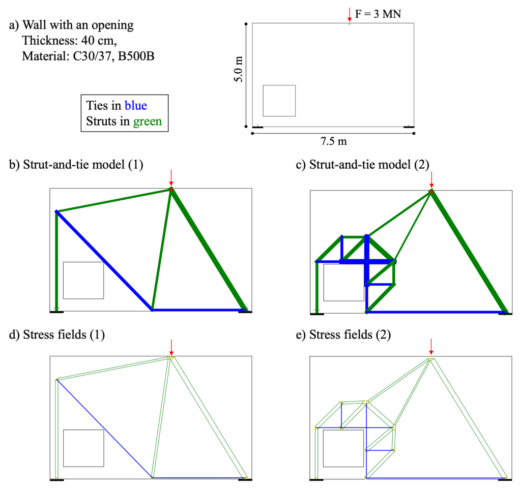
Using the example of a wall with an opening (see Figure 2a, example from Schlaich et al. 1987) and two different corresponding strut-and-tie models3The right concentrated strut is a simplification and one should place transverse reinforcement for spreading the forces., we aim to demonstrate the need for generating multiple strut-and-tie models. The first model (Figure 2b) illustrates a simple yet efficient strut-and-tie model that uses inclined reinforcement and has a low overall steel consumption. Without considering minimum reinforcement, anchoring of the reinforcement, and other constructability issues, the total steel volume is approximately 0.021 m3. The second model (Figure 2c) shows a more regular strut-and-tie model with only orthogonal reinforcement. However, this model uses approximately 70% more steel, resulting in a total steel volume of 0.036 m3. Nonetheless, one should not draw premature conclusions.
The safe application of strut-and-tie models requires the fulfilment of the underlying assumptions of the theory of plasticity, including ductility. Providing sufficient minimum reinforcement, e.g., here 12@150, is non-negotiable. As strut-and-tie models are based on linear elastic material behaviour, they can be superimposed. By considering the minimum reinforcement, the load-bearing capacity of the second strut-and-tie model could be utilised by about 9%. This decreases in combination the load for the first model, ultimately leading to an overall reduction in the steel volume of about 10%. There are of course other possible allocations, e.g., Schlaich et al. propose to have each model carry half of the load. This example demonstrates that it is optional to consider just one optimal strut-and-tie model; instead, several can be combined to take advantage of each model.
The validation tool shows the equivalent stress fields in Figures 2d and e, assuming an anchoring of the reinforcement outside the nodal zone and hydrostatic nodes. It indicates whether enough concrete can be activated in the nodes and makes therefore critical areas more evident to the user.
In conclusion, this example illustrates the trade-off between a simpler strut-and-tie model (1), which optimizes steel usage but may compromise constructability, and a more regular strut-and-tie model (2) with higher steel usage but easier construction.
As a next step, we explore different machine learning tools to tackle the problem of AI-assisted automated strut-and-tie model generation. However, this will be the topic for a future blog post. In the meantime, feel free to reach out to Karin Yu if you have any suggestions or comments.
Karin Yu
Link zur deutschen Version: Einrichtung einer hochschulübergreifenden Gruppe für Forschung und Lehre im Bereich des konstruktiven Mauerwerkbaus.
Teaching and research in structural masonry have a long tradition at the Institute of Structural Engineering at ETHZ. Various pioneering works to describe the load-bearing behaviour of masonry and groundbreaking experimental investigations on masonry were carried out from the 1970s onwards under the direction of Prof. Dr. Bruno Thürlimann and his successor, Prof. Dr. Peter Marti. This work was widely accepted in the scientific community, and it provided the basis for today’s design code SIA 266 and was continued at ETHZ by Dr. Nebojsa Mojsilovic as well as Prof. Dr. Joseph Schwartz. The retirement of Prof. Schwartz at the beginning of 2023 and the upcoming retirement of Dr. Mojsilovic in 2025 prompted the Brick Industry Switzerland (Weblink) to seek a solution to ensure a continuation of the teaching and research activities in structural masonry.
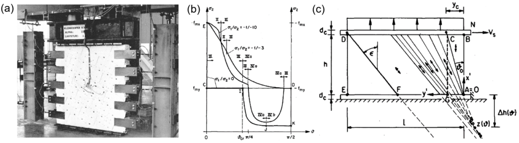
Establishment of an inter-university masonry group
Prof. Dr. Walter Kaufmann (head of the Chair of Concrete Structures and Bridge Design) asked me whether I would like to take over the teaching and research activities in the field of structural masonry. In a few discussions with the Brick Industry Switzerland, the idea of an inter-university masonry group finally grew, which I will lead at the Chair of Concrete Structures and Bridge Design (Weblink) at ETHZ and the Institute for Civil Engineering (IBI) at Lucerne University of Applied Sciences and Arts (HSLU T&A). The masonry group is supported by a generous donation from the Brick Industry Switzerland, whereby the agreement – following our academic principles – guarantees our freedom of research and teaching at all times. Until his retirement, Dr. Mojsilovic will support the masonry group with his valuable expertise, ensuring continuity of the work and tradition.
The fascination of masonry – an ancient construction method in the modern world
Since my studies, masonry has accompanied me in various teaching and research activities, especially during my doctorate at the Institute of Construction Materials (IWB) at the University of Stuttgart (see list of publications here). In addition to numerous analytical and experimental investigations, I was fascinated by using state-of-the-art simulation tools in the analysis of the load-bearing behaviour of masonry and mixed systems (masonry/reinforced concrete) – or, in more technical terms, the development of mechanically consistent models and their implementation in numerical methods (e.g. linear/nonlinear finite elements → see blog post from 2022). In addition, I repeatedly had the pleasure of passing on knowledge through lecturing and co-supervising student projects.
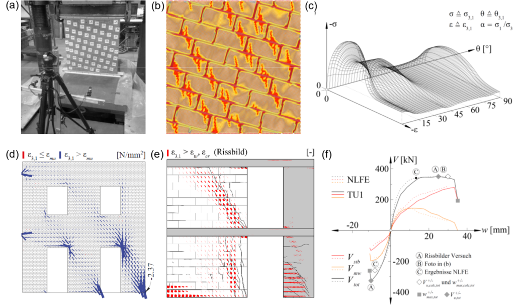
Although masonry construction 1In the context of this blog post, masonry is used as a collective term for all types, combinations and arrangements of masonry blocks and mortar. has evolved over thousands of years, the basic principle (the stacking of stones 2Nowadays, however, a wide range of high-performance bricks are available, depending on the structural, building physics and aesthetic requirements.) has hardly changed over the cultural-historical civilisations – however, the way of analysis, investigation and calculation did so radically. While the Romans and Greeks had already recognized the self-supporting form of masonry vaults in ancient times, scholars in the Renaissance first systematically studied the question of an arch shape adapted to the force flow, from which the concept of the thrust line later developed – i.e. the theoretical line in a structure that represents the path of the compressive force resultant (see Figure 3 (a)). The related mechanical principle of the force transfer via compression struts is still used today for the analysis of masonry structures, for example when assessing masonry arch bridges using graphical statics or in the design of conventional masonry walls based on stress fields according to SIA code 266 (see Figure 3 (b)). However, the methodology for calculating the force flow and the ultimate loads has changed fundamentally due to the digital revolution in recent years. Computers efficiently take over complex computations and routines – however, the art and knowledge of structural and mechanical principles are not superfluous but indispensable for interpreting the results (and more demanding than ever!). Today, even conventional computers have sufficient power for the use of sophisticated (e.g. nonlinear) material models, which allows the force flow to be computed “automatically” 3“Automatically” refers to the computer’s calculation and optimization process. However, applying, interpreting, and verifying such refined models (notably the nonlinear finite element method) is highly time-consuming and requires in-depth expertise. (see Figure 3 (c)) and predictions can be made on the load-deformation behaviour, crack formation and the resulting redistribution of internal forces (e.g. with the URM-Usermat developed during my dissertation for the nonlinear finite element analysis of generally loaded 4Under a general stress state, it meant a shell loading. masonry structures). Given these developments, education and research in the field of structural masonry must not stop – the consistent application of the equilibrium and basic mechanical principles is, however, decisive (or rather mandatory) for their success.
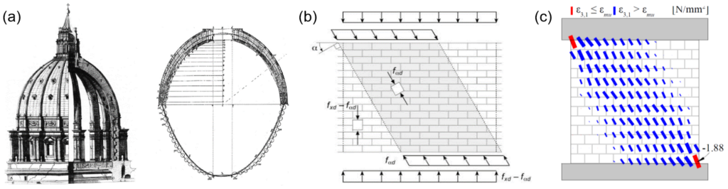
Combine research, teaching and practice
The main task of the masonry group is teaching and research in structural masonry, which are established simultaneously at the chair of Concrete Structures and Bridge Design at ETHZ and at IBI at HSLU T&A. The focus is mainly on promoting and developing numerical simulation tools for solving practical problems.
The research focus is on the development of mechanically consistent material models and their implementation in the software and analysis tools developed by the chair of Concrete Structures and Bridge Design – such as the open-source toolbox StrucEng Library, which is currently under development (more on this in the blog post from 2022). The tools aim at designing new structures more efficiently and identify existing structures’ load-bearing reserves to minimize strengthening without compromising structural safety and robustness. As a basis for developing and validating the material models, we conduct experimental investigations on the load-bearing behaviour of masonry. For this purpose, the unique Large Universal Shell Element Tester (LUSET) is available at the Chair of Concrete Structures and Bridge Design, which allows us to experimentally investigate the load-bearing behaviour of generally loaded shell elements made of masonry for the first time (see Figure 4 (b)).
Furthermore, we address open questions towards the mechanical load-bearing behaviour in structural masonry that have not yet been fully clarified. These include, for example, the question of the application limits of the lower bound theorem of limit analysis (a “sufficient” deformation capacity is assumed) to masonry with its well-known strongly limited deformation capacity or the load-bearing behaviour of hybrid masonry and reinforced concrete structures (e.g. load distribution through the reinforced concrete slabs, involvement of reinforced concrete walls, influence of lintel and parapet elements). To answer the related questions, we combine numerical tools and mechanical modelling with large-scale tests to derive appropriate design models and criteria with direct benefits for engineering practice. The focus is always on the consistent application of mechanically based models.
In the future, we will also increasingly focus on the application and integration of software tools in the digital planning, production and maintenance processes. We will develop new innovative solutions for digitally (pre)fabricated masonry components.
A main concern of the masonry group is ensuring the transfer of research results and disseminating knowledge into engineering design and verification practice. On the one hand, this includes the future provision of the StrucEng Library as an open-source toolbox. On the other hand, we conduct lectures and courses at ETHZ and HSLU T&A, training civil engineers in designing and assessing masonry structures, including the use of computer-aided analysis and design. Furthermore, we are involved in professional associations and code commissions, such as the SIA Group for Preservation of Structures (FEB) and the SIA 266 code commission (Weblink) and work closely with industry on sustainable solutions for construction practice.
Last but not least, the masonry group is intended to be a platform for exchange and discussion in structural masonry, and we invite you to collaborate on solutions for current and future challenges. We are pleased to be able to actively shape the future of masonry and thank the Brick Industry Switzerland for its valuable support. Let’s give masonry a new shine!
Marius Weber
Link zur deutschen Version: Der Weg zu nachhaltigeren Betondecken mittels digitaler Fertigung
Greenhouse gas emissions must be drastically reduced in the face of the climate crisis. The building industry, accounting for around 37 per cent of global operational energy- and process-related greenhouse gas emissions, must become more environmentally friendly, especially considering the increasing demand in floor area in the coming years (2022 Global Status Report for Buildings and Construction). A change of mind is necessary at all levels to achieve this reduction in negative environmental impacts. While alternative building materials are currently receiving a great deal of attention in academia and industry, implementing efficient load-bearing structures is an often-underestimated measure with enormous saving potential. (The Institution of Structural Engineers, 2022)
Given that around half of the material in a typical building is used in floor slabs (Bischof et al. 2022), striving for optimisation of material efficiency in these structural elements is evident. In fact, there are numerous tried-and-tested floor slab systems resulting in massively reduced greenhouse gas emissions compared to the widespread flat slabs: By choosing statically efficient structures such as ribbed slabs, waffle slabs or hollow core slabs, up to 60% of greenhouse gas emissions can be saved compared to flat slabs, depending on the span (Regúlez et al., 2022). So why do we still predominantly build flat slabs nowadays?
This question can be answered with a holistic view of the problem: Floor slabs are not or only conditionally chosen because of their greenhouse gas emissions, but rather criteria such as construction costs, construction time, sound insulation, the possibility of integrating building services components and many others are decisive. In other words, floor slabs must be environmentally sustainable (including emissions, resource consumption and waste production, durability and, where appropriate, circularity), socially sustainable (including safety, functionality and adaptability) and economically sustainable (including cost, construction and flexibility) to be suitable for the mass market. Only systems suitable for the mass market can have a lasting positive impact. The complexity of these requirements is summarised in Figure 1.
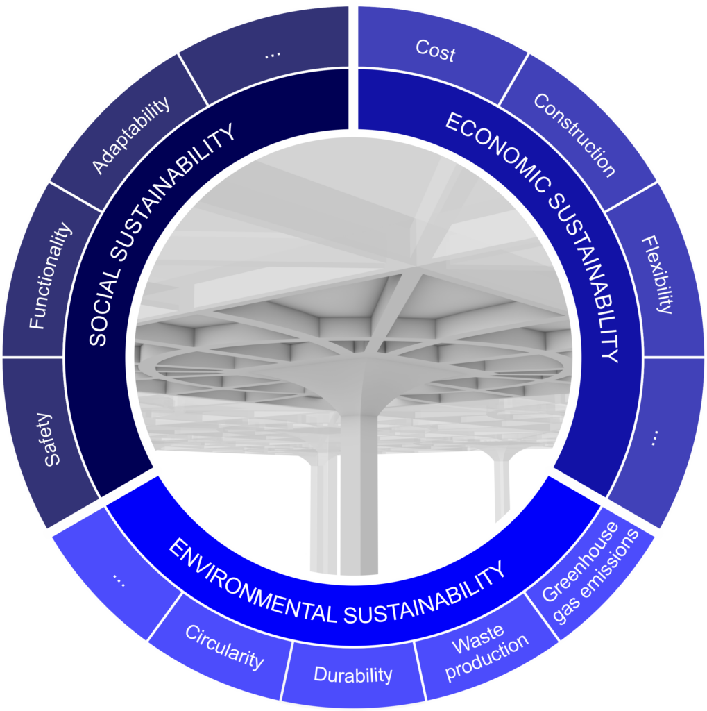
For many of these criteria, choosing a flat slab, whose production has been optimised for decades, is advantageous: Not only are flat slabs inexpensive to build, but they also have a low overall depth and good acoustic sound insulation properties and offer the possibility of integrating building services as inserts. The geometric freedom in the floor plan, made possible by flat slabs, should also not be underestimated: The static efficiency achieved with load-bearing systems such as ribbed slabs often requires cross-sections with greater geometric complexity. Due to the more labour-intensive formwork required, such slabs are generally not produced in situ but are fully or partially prefabricated using reusable formworks. These reusable formworks are generally only suitable for regular and repetitive floor plans, causing a reduction in the geometric freedom of the plan layout. Also, the load transfer in slab systems such as ribbed slabs and hollow core slabs is generally one-way (in comparison with two-way spanning flat slabs), further limiting the geometric freedom in the floor plan.
All these reasons lead to emission-intensive flat slabs being chosen, despite the increased awareness of sustainability in recent years.
The innovative field of digital fabrication with concrete (DFC) could potentially contribute to a more frequent choice of efficient load-bearing systems in the future: Through a variety of fabrication technologies, of which 3D concrete printing (3DCP) is the best-known, the fabrication of geometrically complex, customised structures should be possible without or with minimal formwork, while reducing production costs and increasing worker safety (Wangler et al., 2016). The potential impact of this geometric freedom in practice can be seen in Figure 2: For a floor plan, a flat slab, a ribbed slab with straight, regular ribs and a free-form ribbed slab, as it could be potentially produced with the help of digital manufacturing methods, were pre-dimensioned. Due to the more direct load transfer, the potential material savings with the free-form ribbed floor slab are larger than with the ribbed slab with straight ribs (27% – 38% instead of 18% – 28% reduction in concrete slab volume). Also, there are fewer adjustments to the floor plan (such as additional columns).
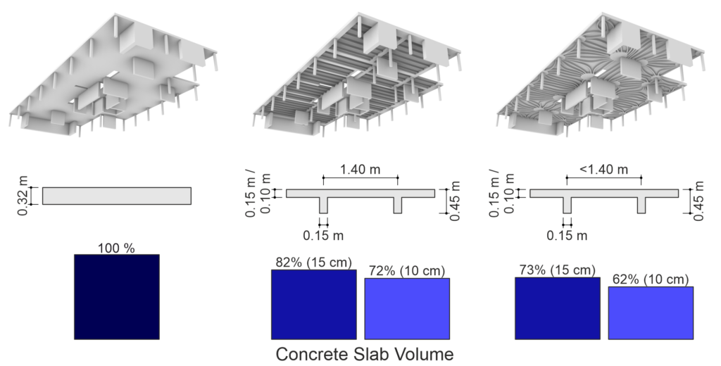
Finding reliable and efficient methods and workflows to produce such or similar geometrically complex structures using DFC is key. In fact, the first concepts for digitally fabricated concrete floors have already been developed both at ETH (within the NCCR Digital Fabrication) and worldwide (see Figure 3). However, it is still a long way from these prototypes, often requiring enormous amounts of manual labour, to a system suitable for the mass market that exploits the possibilities of digital fabrication. We want to proceed along this path by developing systems that use DFC only where the geometric freedom gained is beneficial, thus combining the advantages of DFB and conventional construction methods.
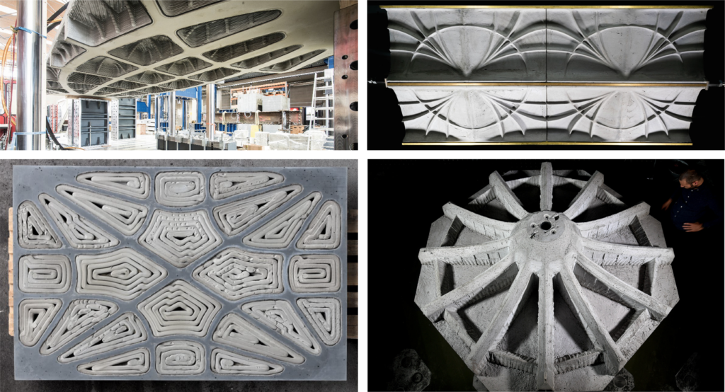
The variety of requirements floor slabs need to fulfil, combined with the possibilities and challenges that DFC entails, make this research project a complex and exciting task – we look forward to updating you about the project’s progress in due course.
Rebecca Ammann
Link zu der deutschen Version: Herstellung eines CFK-vorgespannten Bahnbrückenprototyps.
Some time has passed since the last blog post on this topic, and the project team consisting of SBB, alphabeton AG, HSLU, Empa and ETH has made considerable progress towards their goal of prestressing railway bridges in the span range of 2-10 m with carbon fibre-reinforced polymer (CFRP) rods. The most recent progress is the construction of a 1.7 m x 6.5 m biaxially CFRP-prestressed prototype representing a sector (four instead of nine longitudinal girders) of an overpass with 6 m span. The prestressing is designed to avoid cracking under service loads (LM1). Figure 1 shows the basic idea of the bridge system with the stainless reinforcing steel and the sand-coated CFRP prestressing rods.
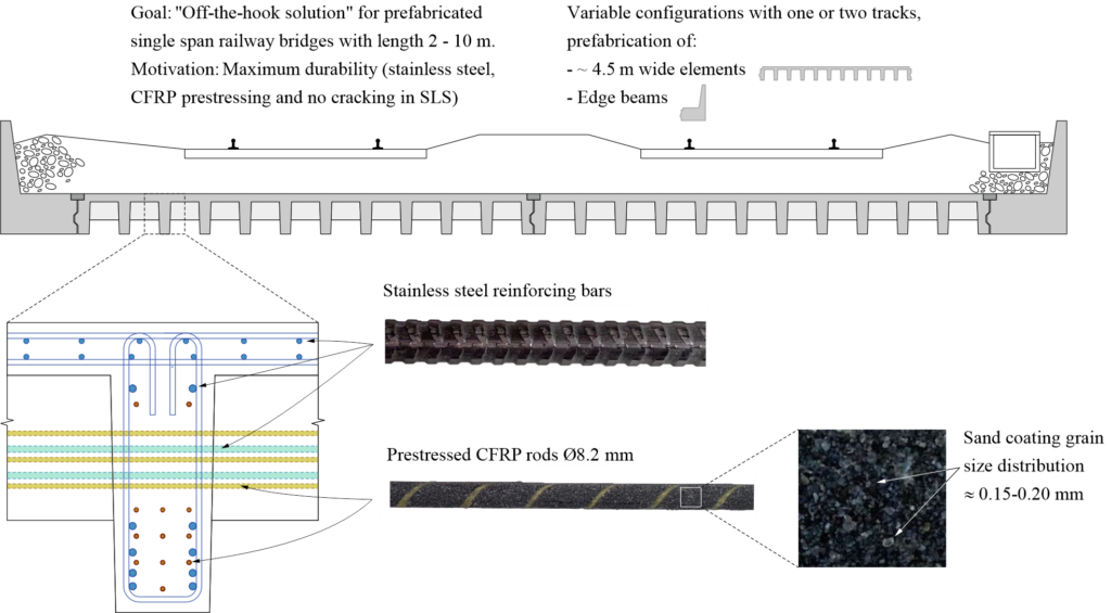
Figure 2 shows the reinforcement detailing in the cross-section of the prototype. It contains the following elements:
- CFRP prestressing rods (longitudinal prestressing Pos. (1), transverse prestressing Pos. (2))
- Bending reinforcement of the longitudinal (101) and transverse (201) girders (1.4362 duplex steel)
- Stirrups and bridge deck reinforcement (made out of B500B steel in the prototype due to cost)
- T-head bars in the intersections of the longitudinal and transverse girders (Pos. 212)
- Lifting anchors in the outer girders
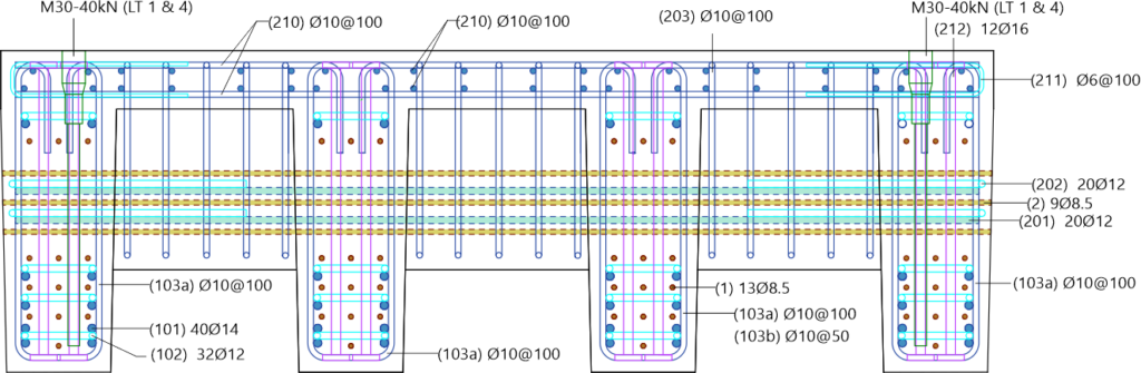
Two important changes to the concept and the production process have been made since the last blog post:
- Instead of ultra-high performance concrete (UHPC), high performance concrete C80/95 was employed. Preliminary tests have shown that this concrete is sufficient to anchor the pretensioned CFRP rods via bond – at a significantly lower cement content.
- The production was staged: The longitudinal girders (two behind each other pretensioned with the same rods) were cast in a first step. After the production of the four longitudinal girders, they were placed next to each other to cast the prestressed transverse girders (prestressing rods and reinforcement through recesses in the longitudinal girders) and the deck slab.
Extensive technology development and preliminary works were required for the production of the prototype. The first challenge was the design of the tensioning frames for pretensioning the longitudinal and transverse girders, realised by Prof. Dr. Albin Kenel and Martina Rohrer, HSLU. Figure 3 shows renderings of the tensioning frames. The frame for the longitudinal girders (Figure 3 (a)) is in total approximately 14 m long (the modular design enables arbitrary lengths <14 m) and designed for a total prestressing force of 2.8 MN. The frames for the transverse direction (Figure 3 (b)) have to resist considerably lower forces (~0.8 MN). All frames have identical systems: The CFRP rods are anchored in perforated plates, which are pushed with hydraulic jacks to reach the desired prestressing force in the rods. Subsequently, the girders are cast around the pretensioned rods, which are released when the concrete has reached the required strength.
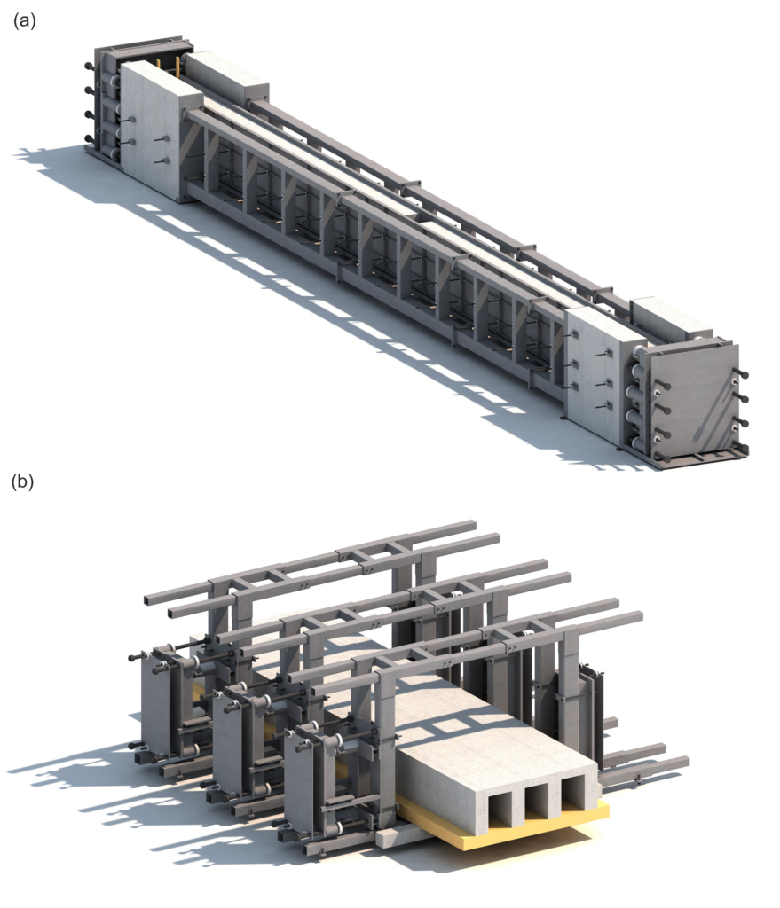
The second challenge was the development of the wedge anchors for the CFRP rods, which are difficult to pretension due to their anisotropy. The anchor system (developed by Prof. Dr. Giovanni Terrasi and Valentin Ott, Empa) consisting of a steel barrel and three polymer wedges is able to reliably anchor 55 kN per rod (equivalent to 1041 MPa on a nominal diameter of 8.2 mm). Figure 4 shows (a) a single anchor, (b) the hydraulic pressing of the wedges into the barrel, and (c) the arrangement of the anchors on the perforated end plate for the production of the longitudinal girders.
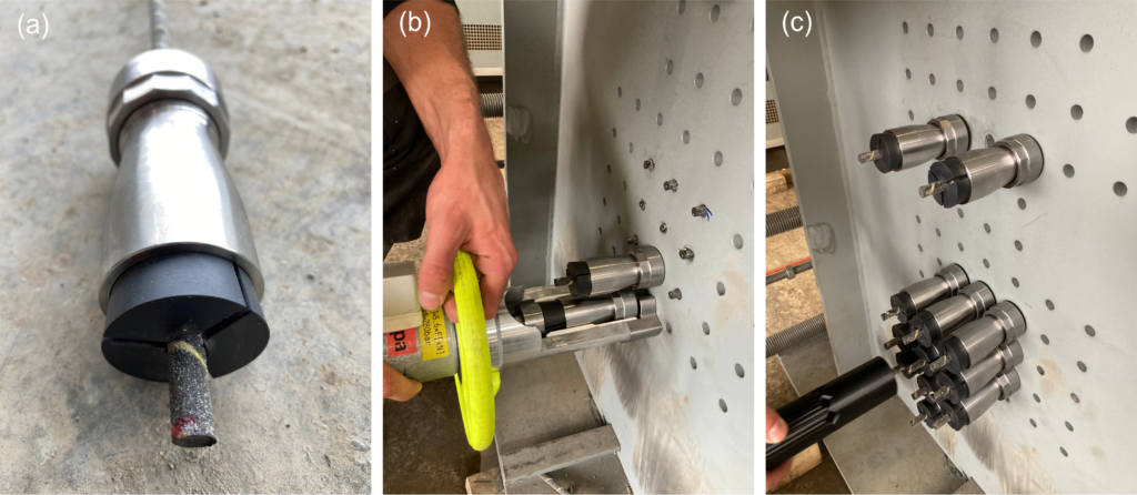
Figure 5 shows pictures of the production in the prefabrication plant of alphabeton AG:
| (a) | Reinforcement cages of the longitudinal girders in the tensioning frame. The cages had to be manufactured very precisely to avoid any contact between reinforcing steel and CFRP rods which would lead to (i) uncontrollable deviation forces and in the worst case rupture of the rods, and (ii) increased risk of galvanic corrosion of the reinforcing bars. |
| (b) | Reinforcement cages with the lower layers of the CFRP prestressing rods with the perforated formwork for the girder ends. |
| (c) | Reinforcement cage with CFRP prestressing rods. |
| (d) | Detail of the recesses with the T-head bars in the intersections of the longitudinal and transverse girders and specifically for this purpose (at Empa) 3D-printed spacers which could be mounted onto the longitudinal reinforcing bars. In this manner, the required precision of the recesses for the transverse prestressing could be assured. |
| (e) | Longitudinal girders in the scaffolding after casting. |
| (f) | Placement of the longitudinal girders in the frames for transverse prestressing. |
| (g) | Reinforcement of the end girders and the deck slab. |
| (h) | Wedge pressing for the transverse reinforcement. Note that massive steel plates were mounted to the frames during tensioning to prevent uncontrolled projection of the wedge anchors in case of failure of a CFRP rod (see Figure 3). |
| (i) | Detail of the transverse prestressing in the recesses of the longitudinal girders. |
| (j) | Finished prototype: side view. |
| (k) | Finished prototype: view from below with longitudinal and transverse girders. |
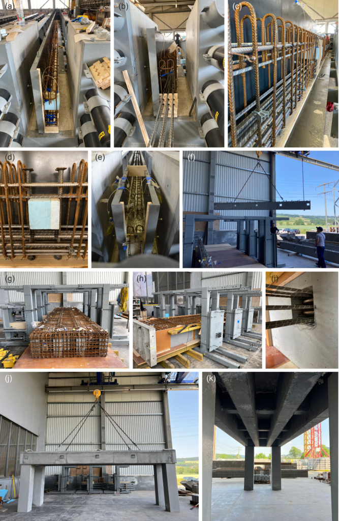
In conclusion, the production of the prototype was successful. Preliminary fibre-optical strain measurements on the CFRP rods show that the prestressing forces are anchored on less than 200 mm via bond, which shows that pretensioning with sand-coated CFRP rods works. The “lessons learned” until now include the design as well as the implementation. Static efficiency and complexity of the production must be carefully balanced; a little more space between CFRP and reinforcing bars would have facilitated the production substantially. Pretensioning the CFRP rods is demanding and requires – besides tailored hardware such as the tensioning frames and the wedge anchors – very precise work, especially during manufacturing of the reinforcement cages. From the point of view of the project team, alphabeton AG has provided the proof of concept for the production, however, the path towards constructing the first CFRP-prestressed railway bridge is still long… Stay tuned!
Andreas Näsbom
Link zu der deutschen Version: Innovation für den Brückenentwurf: Das Potential von KI-gestützter Tragwerksplanung
Bridges are vital infrastructural elements that connect communities, facilitate transportation, and contribute to economic development. The design and construction of bridges require meticulous planning and engineering expertise to ensure safety, efficiency, durability and also aesthetics. So far, this process was heavily reliant on human expertise and manual iterations across multiple teams, resulting in a lengthy and rather rigid design process. Recent advances in artificial intelligence (AI) have already transformed many research and industry fields and have the potential to revolutionize the way engineers conceptualize, analyse, and optimize bridge structures and beyond.
At our Chair, we are working on the integration of modern AI algorithms into structural engineering. Specifically, our ongoing research project “Domain-Aware-AI Augmented Design of Bridge Structures (DAAAD_Bridges)” deals with the implementation of generative AI algorithms for the application in bridge design. Together with the Swiss Data Science Center, we are developing a deep-learning-based software toolbox which aims to function as a co-pilot in early design stages, combining the strengths of AI and humans. Today’s practice is to use simulation software (e.g. finite element software) to evaluate the performance of a specified design. Important design performances include structural safety, serviceability, sustainability, constructability, and cost minimisation. However, detailed and accurate design evaluation via simulation software becomes computationally expensive when applied to complex and high-dimensional design problems such as bridge structures. Using state-of-the-art simulation software renders time-consuming or even infeasible, especially for the case of exploring and comparing multiple design alternatives efficiently in the conceptional design, cf. Figure 1. However, early design decisions are key and performance-decisive for the entire construction project.
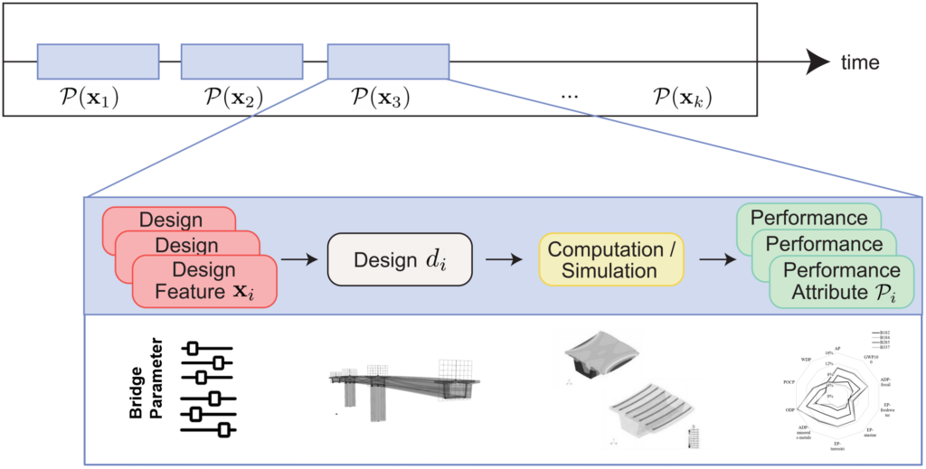
We tackle these challenges and reformulate and augment the current design process with data-based insights, cf. Figure 2. We focus on bridge designs allowing for a parametric representation and develop deep-learning models as surrogates for predicting the performance of specified designs (“forward design”), while additionally enabling the generation of high-performing design alternatives conditioned on a set of performance constraints (“inverse design”). Specifically, the forward design model takes design features (e.g. girder height, number of piers, material strength, etc.) as input and then predicts the performances (e.g. structural utilisation, global warming potential, cost, etc.) of the specified design. The inverse model innovatively allows for the generation of a range of design alternatives based on (self-defined) design objectives and constraints (e.g. budget, structural utilisation constraints, clearance height, etc.).
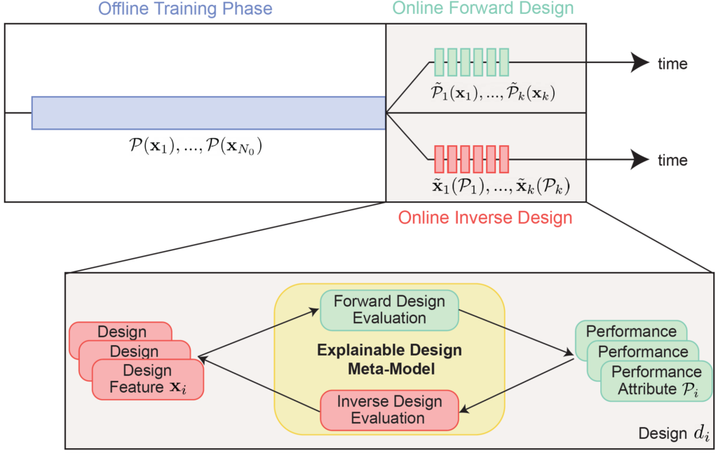
We derived a variant of a conditional variational autoencoder (CVAE), cf. Figure 3, which forms the basis of these design meta-models. The CVAE can be trained on a data set of existing and/or synthetically generated bridge structures. During the training, the model parameter (weights and biases) of the CVAE are fitted to the training data by minimising the loss function defined in Figure 3. The encoder learns the mapping from the euclidean vector x to the corresponding performance vector ŷ (forward design). Simultaneously the decoder learns to generate new design feature vectors x̂ conditioned on the selected performance vector y (inverse design). Subsequent to the training the model is evaluated on a test data set, that consists of bridge structures which the model has not seen before. Additionally, with neural networks being fully differentiable, the CVAE leverages Automatic Differentiation (AD) for the efficient computation of derivatives of the performance metrics w.r.t. the design variables (i.e. for a subsequent local sensitivity or uncertainty analysis.
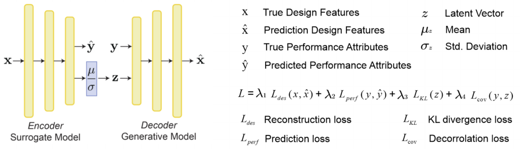
A pilot study was conducted with Basler & Hofmann, where the developed tools were applied to the project situation of a pedestrian bridge in St. Gallen [2]. Using Dynamo within Revit and SOFiSTiK a data set was generated for the real-life project situation at hand, based on which the CVAE was trained. In the project, we also delivered a first version of a graphical user interface, which facilitates first interactions between bridge engineers and the AI model, cf. Figure 4. It was shown that both the forward and inverse mappings can be learned accurately with our CVAE and its design performance prediction (incl. structural utilisation, material volume and cost), as well as the conditioned design generation, is possible in real-time. The model, therefore, allows for rapid exploration of a large number of design alternatives and to identify optimal designs that meet the given performance objectives. By applying sensitivity analysis the trained models provide an understanding of the dependencies of design features and performances of the high-dimensional design spaces and allow for the derivation of design rules for the analysed structures. The tool can therefore boost key decisions in the conceptual design stage of a construction project and hence promote structures that are characterized by efficiency, economic viability, and environmental sustainability. The limitation is that the set-up of the data generation pipeline, the data generation and the training process itself (i.e. the offline phase, cf. Figure 2) require a considerable amount of time. Therefore, the data-based design models should be as generally applicable as possible, which can be achieved for example by expanding the training database to include multiple project situations and bridge structure types. The study also shows the need and potential for systematic and detailed databases of the planned and built structures of today and to come.
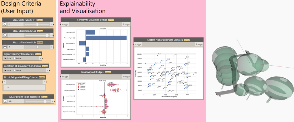
The software toolbox in development is structure-agnostic and can therefore augment a wide range of parametric design problems. We demonstrate the broader applicability of our approach with multiple design application studies: For example the design of steel and timber grid shell structures in cooperation with the Digital Structures group from MIT [3] and the timber connection design with the Timber Structures group from ETH. Sounds interesting? Feel invited to have a look at the project homepages or reach out to us if you are interested to apply our toolbox in your research project or your ongoing project in industry.
Sophia Kuhn
Literature
| [1] | Kuhn, S. V., Hodel, A., Bischof, R., Balmer, V. M., Perez Cruz, F., Kaufmann, W., Kraus, M. A. (2023). Assessment and Integration of Sustainability and Circularity Metrics within Generative Bridge Design. International Conference on Intelligent Computing in Engineering, London. https://doi.org/10.3929/ethz-b-000646105 |
| [2] | Balmer, V. and Kuhn, S. V., Bischof, R., A., Salamanca, L., Kaufmann, W., Perez-Cruz, F., Kraus, M. (2024). Design Space Exploration and Explanation via Conditional Variational Autoencoders in Meta-Model-Based Conceptual Design of Pedestrian Bridges. Automation in Construction, 163, 105411. https://doi.org/10.1016/j.autcon.2024.105411 |
| [3] | Fang,D., Kuhn, S. V., Kaufmann, W. , Kraus, M. A., Mueller, C. (2023). Quantifying the influence of continuous and discrete design decisions using sensitivities. Advances in architectural geometry, Stuttgart. https://doi.org/10.1515/9783111162683-031 |
Links
https://mkrausai.github.io/research/01_SciML/01_BH_PedestrianBridge_XAI/
Link zu der deutschen Version: Entwicklung eines Materialmodelles für zyklisch beanspruchte Stahlbetontragwerke
At the Chair of Concrete Structures and Bridge Design, we have been using an in-house developed material model for the simulations of reinforced concrete (RC) structures for several years, among other things for simulations of existing SBB frame bridges. The simulations are so-called non-linear Finite Element (NLFE) analyses. The term “NLFE analyses” is described in the blog post “Finite Element Method in Civil Engineering“. As stated there, the basic principle of FE analyses in the field of structural engineering is to divide a complex load-bearing structure into many elements (discretisation) and mathematically link the elements to form an overall model. Besides the geometry of the structure, the loading and the boundary conditions/supports, FE analysis also requires a material model to link (at the element level, more precisely at the integration points) the forces or stresses to the deformations or strains. The non-linear material model used at our chair, called CMM-Usermat, accurately simulates the stiffnesses (= force / deformation or = stress / strain) of membrane, slab and shell elements. The structural deformations, failure modes and maximum loads observed in tests are generally well represented by the simulations based on this material model. For a more in-depth look at the structure and verification of the material model, I refer the reader to the following literature: [1]-[4]. The CMM-Usermat is currently limited to unidirectional loads, i.e. only monotonically increasing loads can be considered; unloading and reloading cannot yet be simulated.
As a logical next step in the development of the material model, it should be generalised so that unloading and reloading / cyclic loading can be applied. This allows us to perform simulations of the structures under cyclic loading (e.g. caused by earthquakes) in the time domain, a so-called time history analysis. The scope of my doctorate includes this further development of the RC material model. The research project aims to use the cyclic material model to carry out stable and reliable FE analyses that reproduce the load-bearing behaviour of RC structures subjected to cyclic loading as accurately as possible. Caminada has already addressed this topic during his master’s studies at the Lucerne University of Applied Sciences and Arts (HSLU) and obtained promising results [5]-[7], which justify more in-depth research.
Funding of the research project:
The research project described in this blog post is funded by the Swiss Federal Nuclear Safety Inspectorate (ENSI) and accompanied by its technical experts. The project is scheduled to run for three years and will end in 2025. ENSI promotes research in the field of seismic verification and analysis of RC structures relevant to its regulatory activities. Further information on ENSI’s research can be found in the annual research and experience report.
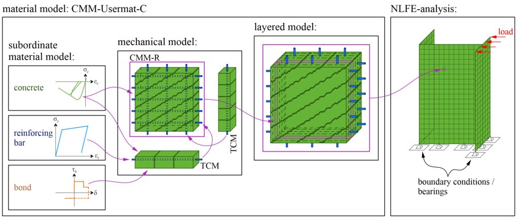
In the following, the structure of the cyclic material model is described, whereby CMM-Usermat-U and CMMUsermat-C denote the unidirectional and cyclic material model, respectively.
RC in a nutshell (for non-civil engineers):
Concrete is relatively strong in compression but an order of magnitude weaker and brittle in tension. The low and uncertain concrete tensile strength is thus commonly neglected at the ultimate limit state. Instead, the concrete is reinforced in at least two (usually orthogonal) directions with ductile steel bars, which have a very high tensile strength compared to concrete. This combination of concrete and reinforcement results in the characteristic structural behaviour of RC: tension is resisted by the reinforcing bars (after the concrete has cracked) and compression is predominantly carried by the concrete.
As highlighted by this brief description of its constituents and load-carrying behaviour, RC cannot be treated as a homogeneous isotropic material. In particular, the interaction of the reinforcing bars with the concrete is highly complex and its modelling requires certain simplifications.
To obtain a good approximation for the complex RC load-bearing behaviour, the CMM-Usermat-C is structured into three levels: subordinate material models, mechanical models and the layered model (see Figure 1).
The subordinate material models describe the stress-strain relationships of the RC components (concrete and reinforcement) as well as the bond stress-slip relationship between concrete and reinforcement. A library of different subordinate material models for concrete, reinforcement and bond is currently being built.
The mechanical models, which form the core of the CMM-Usermat-C, abstract the load-bearing behaviour of RC elements in such a way that the essential mechanisms, including the interaction of the RC components, are represented. The focus is on mechanically consistent modelling in which both the equilibrium of forces and compatibility (strains and stresses comply with the described subordinate material models for reinforcement and concrete at every point in space and time) are fulfilled. The CMM-Usermat-C is based on the Tension Chord Model (TCM) [8], which takes into account the contribution of concrete between cracks (tension stiffening), and the Cracked Membrane Model with rotating, stress-free cracks (CMM-R) [9], which models the load-bearing behaviour of shear-loaded membrane elements. The TCM and the CMM-R access the library of subordinate material models for the material behaviour of the RC components. Side note: The name of the material model CMM-Usermat-C is derived from the mechanical model CMM-R, where “Usermat” stands for “user-defined material”.
The third and highest level in the CMM-Usermat-C represents the layered model [10], which is responsible for extending the mechanical models (1D and 2D) to three-dimensional slab or shell elements. Thereby, the slab or shell element is divided into layers, assuming an in-plane stress state for each layer. The individual layers can be simulated with the mechanical models described above. All resulting forces in the layers are added/integrated and result in the section forces (membrane forces, bending and twisting moment) at a certain point in the FE mesh.
After explaining the overall structure of the CMM-Usermat-C, the next two sections describe the specific extension of the TCM to cyclic loads and the verification of the TCM for cyclic loading based on simulations of a cyclically loaded tension chord test.
Extension of the TCM to cyclic loads
The TCM within the CMM-Usermat-C is used to simulate the relationship between average longitudinal strain and steel stress at a crack for a 1D RC element loaded in tension. An analytical solution for the relationship between average longitudinal strain and steel stress at a crack, as used for unidirectional loading (CMM-Usermat-U), is difficult to achieve for cyclic loading, given the infinite number of possible load histories. Therefore, an algorithmic solution was implemented in which the 1D tension chord is divided into finite slices. Stresses, strains and displacements in the reinforcement and concrete are calculated slice by slice (see Figure 2). It is assumed that the bond shear stress is constant across the thickness of the slices. All variables (σs, σc, εs, εc, us, uc, wr) except the bond shear stress (τb) are evaluated at the grid points between two adjacent slices. Based on the equilibrium of forces, the stresses in the reinforcement and the concrete and the bond shear stresses can be determined. With the subordinate material models, the calculated stresses in the reinforcement (σs,i) or concrete (σc,i) at grid point i can be related to the strains (εs,i, εc,i) and bond stresses (τb,k).
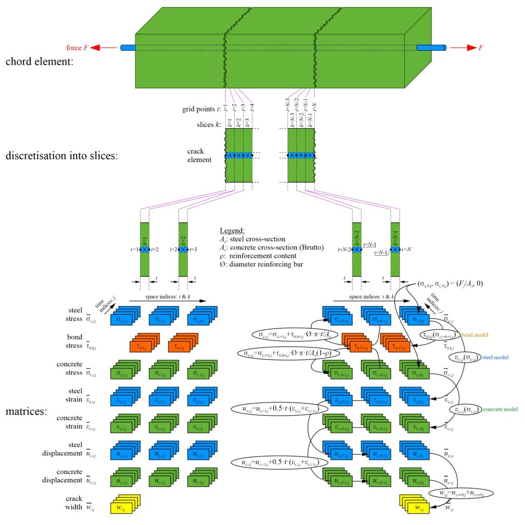
Verification of the TCM for cyclic loading
The cyclic TCM algorithm implemented in Python can be used to simulate tension tests on RC elements. The results of three simulations and one test carried out by Pfyl [11] are shown in Figure 3. The RC tension chord is loaded until cracks form. After a further load increase, the stress in the reinforcement exceeds the yield point. The load is then reduced to zero and increased again until failure is reached. Figure 3 shows that the TCM simulations reproduce the overall behaviour of the experiment well, although there are significant differences between the bond models {full bond; Koppitz et al [12]} and {no bond}. The latter does not consider tension stiffening in the cracked elastic phase and overestimates the deformations in the plastic phase. The TCM simulations with the bond models {full bond; Koppitz et al. [12]} overestimate the energy dissipation during unloading and reloading (hysteresis loop), whereas the bond model {Koppitz et al. [12]}, which considers bond damage after unloading, deviates less from the experimental curve than the bond model {full bond}. The results of the simulations are generally satisfactory.
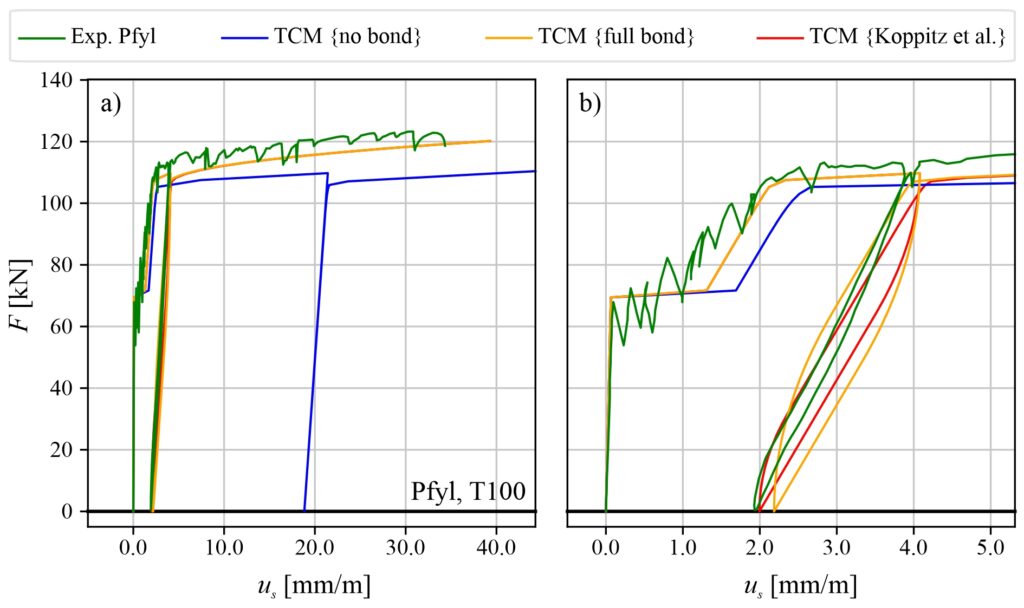
Further descriptions and results will follow as the project progresses.
Simon Karrer
Literatur
[1] P. Roos, “FEM Modelle für Stahlbetonplatten – Verifizierung des Schichtenmodells anhand von Bauteilversuchen”, Hochschule Luzern Technik & Architektur, Horw, 2014.
[2] K. Thoma, P. Roos, and M. Weber, “Finite-Elemente-Analyse von Stahlbetonbauteilen im ebenen Spannungszustand”, Beton- und Stahlbetonbau, vol. 109, no. 4, pp. 275–283, 2014, doi: 10.1002/best.201300087.
[3] K. Thoma, P. Roos, and G. Borkowski, “Finite Elemente Analyse von Stahlbetonplatten”, Beton- und Stahlbetonbau, vol. 109, no. 12, pp. 895–904, 2014, doi:10.1002/best.201400047.
[4] K. Thoma, “Finite element analysis of experimentally tested RC and PC beams using the cracked membrane model”, Engineering Structures, vol. 167, no. 15, pp. 592–607, Jul. 2018.
[5] T. Caminada, “Zuggurtmodell – zykische Beanspruchug”, Vertiefungsmodul I, Fachgruppe Massivbau HSLU, Horw, 2017
[6] T. Caminada, “Normalkraft beanspruchte Betonelemente”, Vertiefungsmodul II, Fachgruppe Massivbau HSLU, Horw, 2017
[7] T. Caminada, “Gerissenes Scheibenmodell für zyklische Beanspruchungen”, Master’s Thesis, Fachgruppe Massivbau HSLU, Horw, 2018
[8] P. Marti, M. Alvarez, W. Kaufmann and V. Sigrist, “Tension Chord Model for Structural Concrete”, Structural Engineering International, vol. 8, no. 4, pp. 287–298, Nov. 1998, doi: 10.2749/101686698780488875.
[9] W. Kaufmann, “Strength and Deformations of Structural Concrete Subjected to In-Plane Shear and Normal Forces”, Doctoral dissertation, Institut für Baustatik und Konstruktion, ETH Zürich, Basel, 1998. doi: 10.1007/978-3-0348-7612-4.
[10] H. Seelhofer, Ebener Spannungszustand im Betonbau: Grundlagen und Anwendungen. Zürich: vdf Hochschulverl. an d. ETH, 2010.
[11] T. Pfyl and P. Marti, Versuche an stahlfaserverstärkten Stahlbetonelementen, vol. 268. 2001. [Online]. Available: https://doi.org/10.3929/ethz-a-004273447
[12] R. Koppitz, A. Kenel, and T. Keller, “Tension Chord Model Modification for Uniaxial Unloading and Reloading in Elastic and Plastic States”, Journal of Structural Engineering, vol. 140, no. 10, p. 04014077, Oct. 2014, doi: 10.1061/(ASCE)ST.1943-541X.0000999.
Link zu der deutschen Version: Traglastverhalten von Stahlbetontübbingfugen
It may be rather surprising that the chair of concrete structures and bridge design is also involved in tunnelling. However, precast concrete tunnel lining segments are frequently used in tunnels built with a tunnel boring machine (TBM) and due to the large number of segments required, optimising the lining segments can have a major impact on the tunnel construction project. Leaner tunnel linings could significantly reduce cost and environmental impact as a thinner lining would not only use less construction material but, more importantly, reduce the required excavation.
The segments take on a wide range of tasks: Absorb the rock pressure, seal the tunnel, serve as a fastening element for equipment, and transmit the drive and control forces of the tunnel boring machine. The corresponding forces must be considered in the design of the segments, for which the joints play a key role.
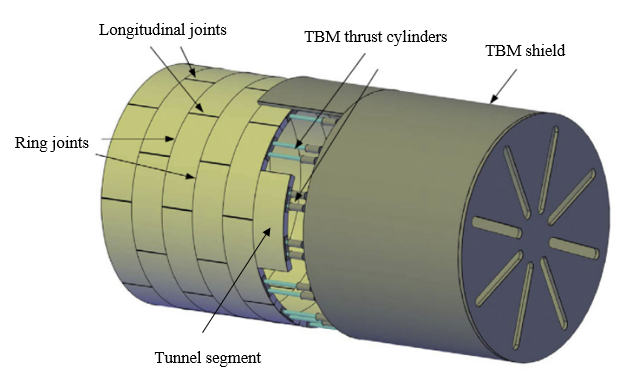
The longitudinal joints between segments (see Figure 1) transfer the loads during construction and the entire service life in one-pass lining systems. Large circumferential compressive forces typically occur in tunnels with significant overburden or squeezing grounds. The contact surface in the longitudinal joints is generally reduced compared to the full cross-section of the segments to ease installation, avoid spalling and place watertight gaskets. Due to the reduced contact surface, compressive stresses are higher at the load introduction area, and splitting tensile stresses occur further away due to the load dispersion. The lining thickness of tunnels with large circumferential compressive forces is often governed by the design of the longitudinal joints.
In shield-driven tunnels, the concentrated compressive loads of the TBM thrust cylinders distributed around the circumference act on the last installed segment ring and are transferred to the previously installed segment rings by the ring joints (see Figure 1). The tensile stresses resulting from load dispersion and assembly tolerances often govern the reinforcement design for crack width limitations.
An ongoing research project at the chair of concrete structures and bridge design, supported by ASTRA and BAV, investigates the longitudinal and ring joints of tunnel lining segments and aims to provide improved design approaches. This blog post focuses on the longitudinal joints and will present results from an experimental campaign.
The structural behaviour of longitudinal tunnel lining joints can be represented as a partial area loading problem, with predominantly unidirectional load dispersion. It can thus be reasonably idealised as strip loading where a member is subjected to a line load, applied over a narrow width and extending over a much larger length, eventually spreading over the whole cross-section. Based on extensive test series, it is known that for partial area loading significantly higher contact pressures than the uniaxial concrete compressive strength can occur. Most current design approaches for partial area loading (e.g. SIA 262, Eurocode 2 and fib Model Code 2010) rely on the so-called square-root equation. It relates the average bearing capacity of the loaded area, expressed as stress qx,u, to the uniaxial compressive strength fc and the square root of the ratio of the area available for load dispersion Ac2 and the loaded area Ac1:
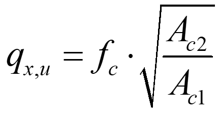
The square-root equation is purely empirical, consequently, standards restrict its use by several conditions: geometrical similarity of Ac1 and Ac2, limitation of the strength increase to a factor of three, and a requirement of transverse reinforcement to account for the bursting stresses. The first condition strongly limits the strength increase for longitudinal tunnel lining joints. The required resistance of the bursting reinforcement can be reliably determined from a simple strut-and-tie model. It is important to mention, that the square-root equation does not consider the beneficial effect of transverse reinforcement located in the vicinity of the load application area, nor that of bursting reinforcement exceeding the minimum amount required. Experiments revealed that longitudinal tunnel lining joints can sustain substantially higher loads than predicted by the square-root equation. However, conducting project-specific tests is expensive and time-intensive.
As an alternative to the square-root equation, longitudinal tunnel lining joints can be designed as structural members with confinement reinforcement, e.g. according to SIA 262, paragraph 4.2.1.8. This is a mechanically sound approach that is mainly used in the design of pre-stressing anchorages and short compression members. This approach enables the activation of transverse reinforcement – both close to the load application and where bursting reinforcement exceeds the minimum amount required for load dispersion. However, it neglects the beneficial influence of load dispersion in partial area loading. In addition, uncertainties exist to what extent the reinforcement can be activated and whether spalling of the cover concrete can already occur in the serviceability limit state. According to SIA 262, combining the square-root equation and the beneficial effect of confinement reinforcement is not allowed. Nevertheless, it is well known that load dispersion and reinforcement positively impact the bearing capacity of partially loaded areas.
Only a few experiments have been carried out on specimens with significant confinement reinforcement subjected to strip loading in the past. Because of this an experimental campaign on 20 strip-loaded reinforced concrete blocks (350x550x525 mm3) was conducted. The samples were tested with a 20 MN Amsler compression testing machine at Empa in Dübendorf, Switzerland (see Figure 2). The specimens were either made of normal-strength concrete, high-strength concrete or fibre-reinforced concrete and were reinforced with welded grids, bent ties or double-headed bars continuously placed in the transverse and longitudinal direction over the full height (see Figure 3). The samples were loaded with small steel bricks over a continuous length of 450 mm and a width of 140 mm or 210 mm, corresponding to load concentration ratios of 40% (= 140 mm / 350 mm) and 60% (= 210 mm / 350 mm), respectively. All specimens but two were centrally loaded.
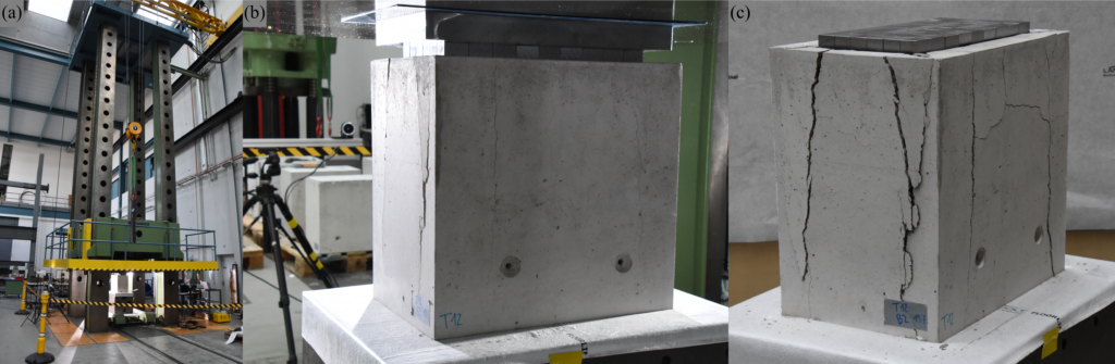
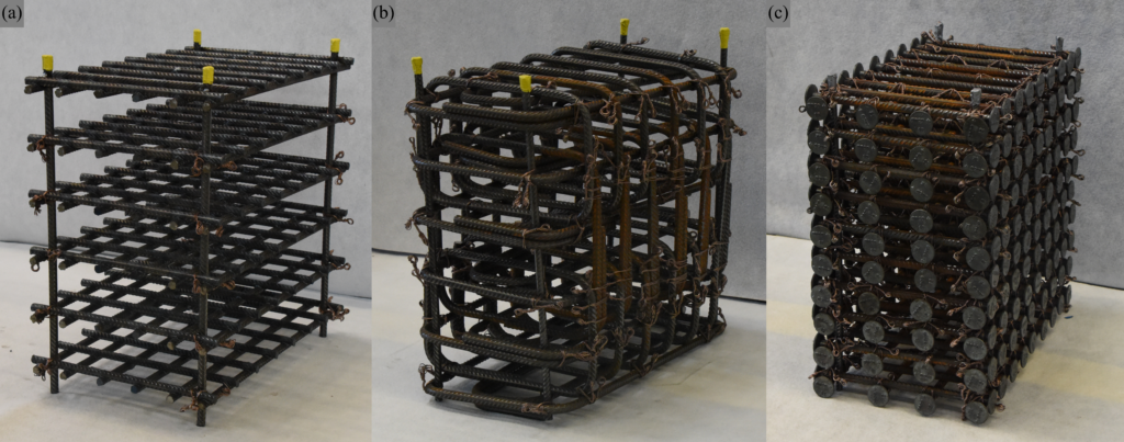
The following conclusions can be drawn from the experimental campaign:
- Increasing the reinforcement amount leads to higher bearing capacities.
- Geometric reinforcement contents up to 4% in the transverse direction can be activated.
- Welded grid reinforcement exhibits similar load-bearing behaviour as bent ties and double-headed bars.
- Samples with hybrid reinforcement (conventional reinforcement combined with steel fibres) sustain higher bearing capacities than samples with the same amount of only conventional reinforcement.
- The bearing capacity of strip loaded reinforced concrete blocks, normalised by the concrete strength, decreases with higher concrete strength.
- A smaller load concentration ratio results in a higher bearing capacity qx,u,exp. Note that despite the increase of the stress qx,u,expwith reduced loading width, the peak load decreases due to the smaller loaded area.
For further details regarding the experimental campaign, the reader is referred to Morger and Kaufmann.
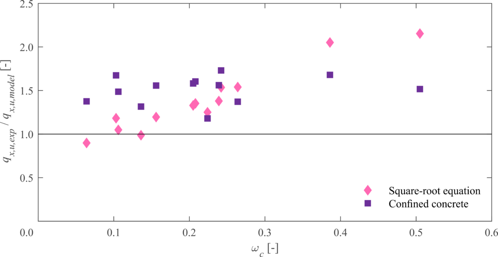
Figure 4 presents the ratios of the experimentally observed average bearing capacities qx,u,exp to those predicted by the different models qx,u,model plotted versus the mechanical reinforcement ratio ωc. Only centrally loaded specimens out of normal and high-strength concrete are shown in Figure 4. For the square-root equation, it can be seen that the reliability of predictions decreases with increasing reinforcement ratios. Note that the condition on geometric similarity was neglected. Otherwise, much more conservative predictions result. Considering confinement, the influence of different reinforcement ratios is captured, but this approach consistently underestimates the bearing capacity since the impact of load dispersion is neglected.
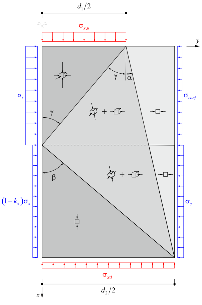
The recently published mechanically consistent Dual-Wedge stress field (see Figure 5 or Markic, Morger and Kaufmann) takes load dispersion and confinement reinforcement into account. In comparison with the square-root equation and the confinement approach, the Dual-Wedge stress field provides accurate predictions of the bearing capacity for strip-loaded reinforced concrete blocks. The detailed comparison of the dual-wedge stress field with the experiments will be presented in an upcoming publication.
On the occasion of the fifth “Betontag”, that took place at the Fribourg School of Engineering and Architecture HTA-FR, the current blog post is dedicated to the Swiss delegation of the Fédération internationale du béton (fib-CH). In an interview, we talked to Thierry Delémont, head of the fib-CH delegation, and Dr Patrick Valeri, who has also recently become a member of the delegation and head of the fib-CH Young Members Group. They present to us the organisation, its tasks, and goals.
In 1998, the Comité Européen du Béton (CEB) and the Fédération Internationale de la Précontrainte (fip) merged to form today’s Fédération international du béton (fib). The CEB, founded in 1953 with the aim of standardising regulations in the construction industry on an European level, published its first recommendations for a set of standards in 1964. In 1978, the publication “International System of Unified Standard Codes of Practice for Structure” followed in cooperation with the fip, which later formed the basis of the Eurocode for structural concrete. Since 1985, the CEB (and today the fib) has been located at EPF Lausanne. What is the role of the Swiss group (fib-CH) in the organisation of the fib?
What is the role of the Swiss group (fib-CH) in the organisation of the fib?
Thierry Delémont: Switzerland played a leading role in the founding process of the CEB and fib, and still forms an important part in the organisation despite the small size of our country. The strategic decisions of the fib are taken annually in the “Technical Council” and at the “General Assembly”. With three delegates, Switzerland is one of the most strongly represented countries. The fib-CH represents this delegation and aims to promote the objectives of the fib at a national level: Promotion of research in the field of structural concrete, dissemination of results in research and development, organisation of congresses, symposia and workshops, development of recommendations at a national and international level, and information of our members about these latest developments.
Our goal is to establish a connection between young professionals and experienced engineers so that the young generation can also play an active role in the association.
Patrick Valeri, you joined the fib during your doctoral studies and took over the position as head of the Swiss fib Young Members Group (YMG). What is the function of the YMG? Who can become a member? And do you have your own agenda and prioritised goals that differ from the rest of the fib?
Patrick Valeri: The core interests and goals of the YMG are the knowledge transfer, networking, the support of the task groups, and organising symposia. Our goal is to establish a connection between young professionals and experienced engineers so that the young generation can also play an active role in the association. According to Tomaž Ulaga, a member of the Swiss delegation, every engineer used to be a member of at least one professional association a few decades ago. Nowadays, the hectic daily work routine takes up much time, and the number of association members is decreasing. The YMG is trying to counteract this trend.
On October 25, 2022, the fifth fib-CH Betontag took place at the Fribourg School of Engineering and Architecture HTA-FR (Figure 1). Since when has this event been organised? What are its objectives, and who is the target group?
Thierry Delémont: The main objective is to present the know-how of Swiss engineers to the international engineering community with a regular publication: Structural Concrete in Switzerland. Despite the fact, that very few Swiss engineers present their projects at fib congresses. In a second step, a regular event is established with the Betontag where industry professionals can meet and exchange ideas.
Patrick Valeri: This publication appears every four years, i.e. in the same rhythm as the fib Congress, which also takes place every four years. In addition, the Betontag establishes and maintains a link between the Swiss delegation of the fib and fib-International.
A selection of the most important projects is published in Structural Concrete in Switzerland and presented at the following Betontag. One of the first Swiss publications, called Spannbeton in der Schweiz, came about as a collection of Swiss contributions from the seventh fip Congress in 1974. This publication included a contribution to the design and construction of the viaduct over the Paudèze, and in this year’s volume, the modernisation of the structure was presented. The Betontag and the publication contribute to maintaining a high-quality construction culture in Switzerland.
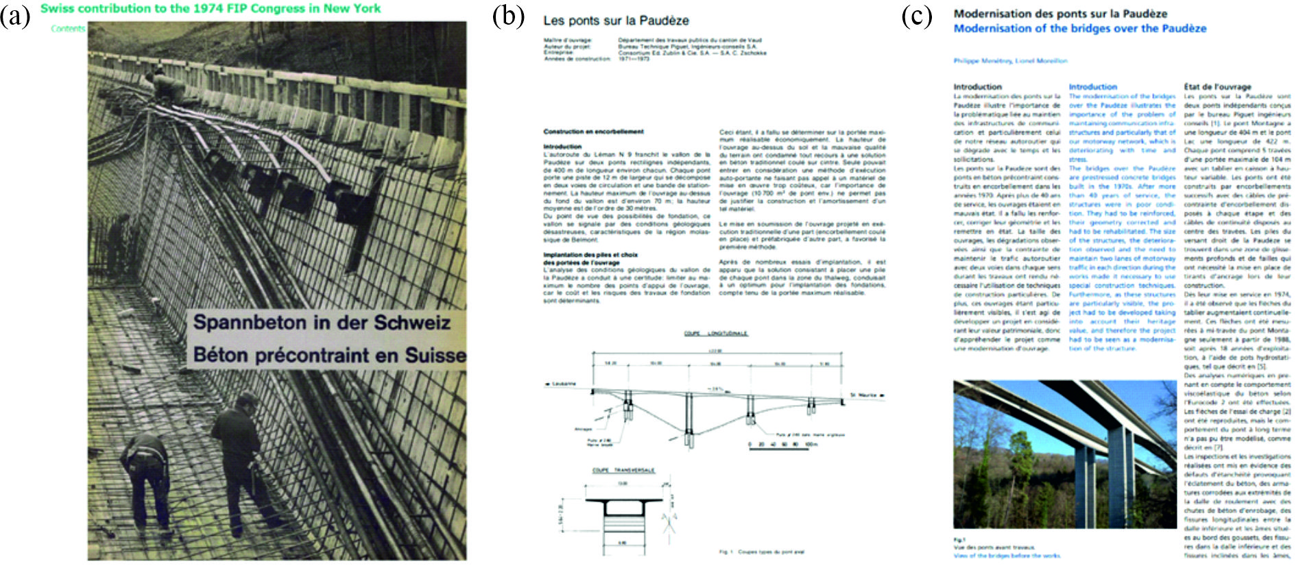
What does the Betontag mean to you personally? Why do you participate?
Thierry Delémont: This day is always an excellent opportunity to meet colleagues you do not see regularly and make new acquaintances. It also offers the opportunity to discover projects from other regions of Switzerland of which you would not hear otherwise. I had the opportunity to present a project at a previous event, but nowadays I participate as an organiser.
Patrick Valeri: For me, the Betontag fulfils numerous functions. On the one hand, it serves as a hub for making new connections and maintaining and cultivating existing acquaintances. Ideally, planners, contractors, owners, and students meet here to exchange ideas informally. This exchange promotes innovation and quality in project planning and execution. On the other hand, we can also let us inspire by the presentations, getting an overview of where we are heading to as a society and on which topics we still need to work.
How have the fib-CH group and the Swiss society of civil engineers in general developed over the last few decades? And where do we want to go from here?
Thierry Delémont: From a personal point of view, I regret that the majority of practising civil engineers in Switzerland is not particularly interested in participating in international exchange through associations such as the fib. Presumably, Switzerland’s privileged position does not encourage engineers to get involved abroad. In contrast, the two technical universities and some universities of applied sciences are very active, thanks to the initiative of their professors, who are much more aware of the importance of international exchange. Therefore, I would welcome it if more practising civil engineers from Switzerland would get involved in fib task groups since they can not only contribute but also learn a lot there.
Where do you locate room for improvement in exchange and cooperation on an international level and between industry and research?
Patrick Valeri: Through digitalisation, we have experienced a general acceleration of our society in recent decades. In my opinion, this can potentially lead to a split between research and practice because standards, guidelines, and market-ready products cannot always be at the latest state of knowledge. Additionally, sometimes different goals are pursued in research and practice (project planning, product manufacturing) because other market and financial forces rule.
The fib-International consists of university professors and engineers, who are active in research, project planning, and product development. The cooperation of these people, who sit down at the same table, tries to counteract this division between research and practice. We have two mechanisms for this: firstly, upcoming research topics can be tailored to practical requirements and market expectations. And secondly, a multitude of scientific publications can be transformed into guidelines suitable for practice (fib Bulletins). In this sense, the fib forms an international framework so that research and practice can work together in synergy.
We live in a globalised world with problems that affect the whole planet. Therefore, solutions also need to be thought of on a global level.
My colleagues are participating this year for the first time in the Betontag. For some of them, this is their first contact with the fib. How important is it to be actively involved, particularly for younger engineers?
Patrick Valeri: In my opinion, it is important for at least two reasons that the young generation is actively involved in an association. First, the established generation will step back and retire in the future. The earlier we, as young engineers, join the association, the longer we can extend this transition phase – and learn a lot from each other during this time. Secondly, association work is also more or less the opposite of our everyday professional life, where projects are handled and completed. In the fib, as in other professional associations, we can share our professional knowledge with our colleagues in a structured framework to benefit from it in the future. In this sense, our work for an association is overarching and an inspiring alternative to our everyday project work.
Thierry Delémont: We live in a globalised world with problems that affect the whole planet. Therefore, solutions also need to be thought of on a global level. It is becoming increasingly important to foster contacts with the entire international engineering community, e.g. through associations like the fib. Therefore, the YMG offers young engineers an excellent opportunity to exchange ideas with colleagues from different countries and, at the same time to make proposals which are heard by the whole fib.
I would like to address one last topic – it is one that concerns me personally: sustainability in the construction industry. The construction industry has an enormous carbon footprint. According to the Federal Office for the Environment (FOEN), greenhouse gas emissions from cement production alone account for 35% of industrial emissions – this corresponds to around 8.7% of total Swiss emissions (2020, FOEN). Prof. Muttoni clearly expressed the urgency in his closing words at the Betontag. What did you take away from this closing speech, and what would you like to share with the readers here?
Patrick Valeri: It is a topic that concerns us all, or at least it should. In essence, Prof. Muttoni appeals to us civil engineers to use resources intelligently and to be innovative. One of the examples he gave was about slab design: a slab made of reinforced concrete with a low cement content, a careful choice of cement type, statically sensible geometry and recycled building materials, especially the reinforcing steel, has a comparable CO2 footprint to a wooden ceiling. With optimisations, it is quite possible to save 80% kg CO2 equivalent, which is considerable. Timber structures are also very much in vogue. However, one should not forget that wood is in limited supply and cannot replace concrete in all its functions. This is the case with most road and railway bridges, earth retaining structures, earthquake bracing of high-rise buildings and the like, to name just a few examples. Nevertheless, the trend towards hybrid reinforced concrete and timber structures is positive. The fib actively supports this trend: at the Conceptual Design Symposium 2021 in Attisholz, several contributions were presented on the design of timber-concrete hybrid structures, such as the Holliger Tower presented by Dr. Neven Kostić (see video).
What should also resonate from the closing words is the importance of a holistic engineering approach as a means for more sustainability. Overall performance competitions are excellent methods for project optimisation and provide room for innovation and material savings. It would be essential to evaluate and take into account the ecological impact of construction projects. In this sense, however, all those involved, i.e. the owners, engineers, contractors, and cement producers, must work towards a more sustainable goal and innovative and efficient solutions.
Tena Galkovski
The interviewees:
Thierry Delémont
Ing. Civ. Dipl. EPF / SIA
Delegationsleiter fib-CH
Managing director at T ingénierie sa
Dr. Patrick Valeri
MSc ing. civile PoliMi / SIA
Delegationsmitglied fib-CH
fib YMG-CH Vorsteher
Projektleiter Dr. Lüchinger+Meyer Bauingenieure AG
Link zur deutschen Version: Schalung als zentrale Herausforderung bei der Herstellung von effizienten, wirtschaftlichen und nachhaltigen Betondecken
The current environmental crisis urges the construction of more sustainable structures, which requires a radical change in the way we design and build nowadays [1]. Although changes in the construction industry are traditionally slow compared to other industries, such as the automotive or computer industry, there is already (at least) a general agreement in academia about the urge to reduce, reuse, recycle and recover construction materials and structures in order to achieve a radical drop in the CO2 emissions from an industry responsible of 38% of the global greenhouse gas emissions [2][3].
Research groups are making considerable efforts to address the structural and fabrication optimisation of concrete slabs seeking a reduction in material consumption, as these elements generally take between 40 % and 60 % of the concrete in the building’s structure [4]. Furthermore, lighter slabs would transmit lower loads to the vertical structure resulting in smaller dimensions of pillars, walls and foundations.
Structural efficiency is sought through shape, topology and size optimisation, resulting in thin-shell flooring systems of different kinds [5][6], ribbed slabs [7][8] or the combination of both [9][10][11]. Cutting-edge methods and software allow concrete floor models with a maximum degree of structural optimisation. Although innovative uses of digital fabrication are being used, the construction of these usually-complex shapes still presents several difficulties regarding sustainability and economy. While the former requirement is usually self-imposed until stronger sustainability regulations are established, the crude reality of the construction industry reminds researchers who want to spread out their innovations that a system which is not economically profitable has very few chances to enter the mass market and, therefore, have an impact on the society. One of the major challenges concerning these issues is related to the fabrication of the formwork.*
A look into the past can clarify the importance of economic formwork to build non-straight elements, mainly vaults and shells. Ancient, great master builders, architects or engineers relied on a specific economic way to fabricate or use the formwork to be able to build their masonry or concrete shells, or, in some cases, they even resorted to techniques which did not require any formwork. Some examples of the many existing ones are featured in the following paragraphs.
After emigrating from Spain in 1881, the Guastavinos (Rafael Guastavino Sr. and his son) built around 1000 buildings in the United States thanks to an economic, expressive and fire-proof construction technique: tile vaulting [12]. Tile vaults (sometimes referred to as thin-tile, timbrel, Catalan or Guastavino vaults) are masonry structures made with thin bricks (tiles), mortar and fast-setting cement or gypsum. The bricks are placed flat, building up to two, three or more courses. Traditionally, tiles are used because of their lightweight, which is a necessary condition, together with the use of a fast-setting binder, to build the first course without supporting formwork [13] [14] [15] (Figure 1).
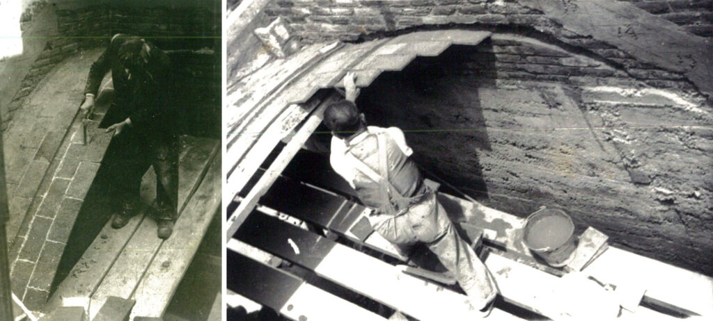
The engineer Eduardo Torroja (1899-1961) also used this construction technique because “such shells [tile vaults] are cheap to make and may be adapted to any desired shape, even to continuously changing curvatures, […]. If constructed by bricklayers skilled in the technique, they can be made without the aid of formwork.” [16]. He used it in combination with reinforcement in, for example, a church in Pont de Suert (Figure 2) or the foundations of the Sancti Petri Bridge in Cadiz, both in Spain [17] [18] [19].
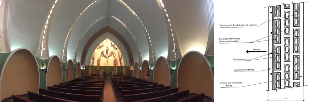
The Italian engineer Pier Luigi Nervi (1891-1979) also made big efforts to achieve economic construction techniques through appropriate formwork systems. Seeking to avoid the massive timber formwork that he used in some of his first hangars for the Italian Air Force, his search led him to the use of prefabricated concrete elements and ferrocement reusable formwork on moveable scaffoldings [20].
Reusable and moveable formworks were also used by the Uruguayan engineer Eladio Dieste (1917-2000) [21]. This fact has an extraordinary impact on the design of his reinforced brick shells, which feature a repetitive rhythm of the same shape along the length of the building (Figure 3). The amount and type of mortar in the bricks’ joints allowed a quick removal of the formwork to be used as soon as possible for the next part of the building [22] [23].
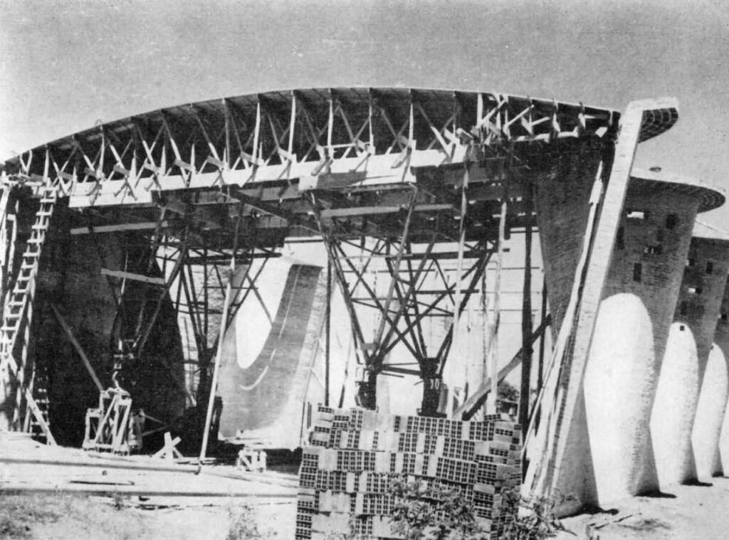
The Spanish architect Félix Candela (1910-1997) achieved economic formworks for his concrete shells by shaping his structures as hyperbolic paraboloids. Such ruled surfaces allowed easy and fast construction of the formwork using only reusable, straight, wooden planks. This system, together with the relatively low labour cost at that time and location, allowed him to have a prolific career building concrete thin-shell structures [25].
Hyperbolic paraboloids were also built by Antoni Gaudí (1852-1926) and Luis Moya (1904-1990) using the tile vaulting technique. Gaudí would use this shape for the tile vaults at the porch of the Colonia Güell’s church in Santa Coloma de Cervelló, Spain [26]. He would then pour concrete on the tile-vaulted integrated formwork to create a hybrid masonry-concrete structure [19]. In the case of the architect Luis Moya, a hyperbolic paraboloid was used to cover the chapel that he designed for the School Santa María del Pilar in Madrid, Spain [27]. This roof is a 743 m2, 14-cm-thick, reinforced tile vault built using a falsework of wooden planks with a separation of 60 cm. Reinforcement is placed in between the courses of bricks while a 10-cm layer of light concrete is applied on top of the masonry [28] (Figure 4).
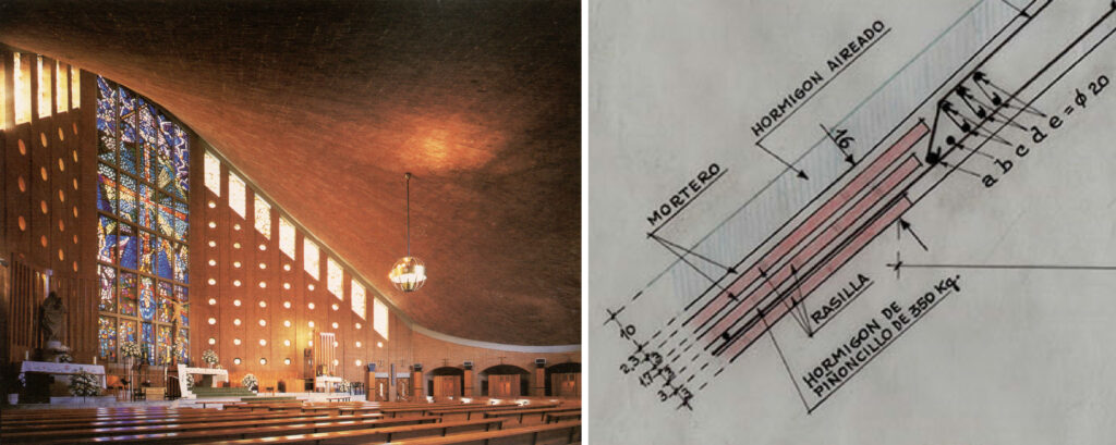
The use of tile vaults as integrated formwork for concrete is a possibility explored by the author of these lines [29]. The research on this topic presents this construction technique as a possible way to build expressive, reinforced concrete shells (including floor systems) using tile vaults as integrated formwork, aiming at reducing costs and material waste while providing a unique finishing at the intrados [30] (Figure 5). The construction costs can be reduced mainly due to the low cost of the materials involved and the fact that no additional formwork or related foundations are needed.
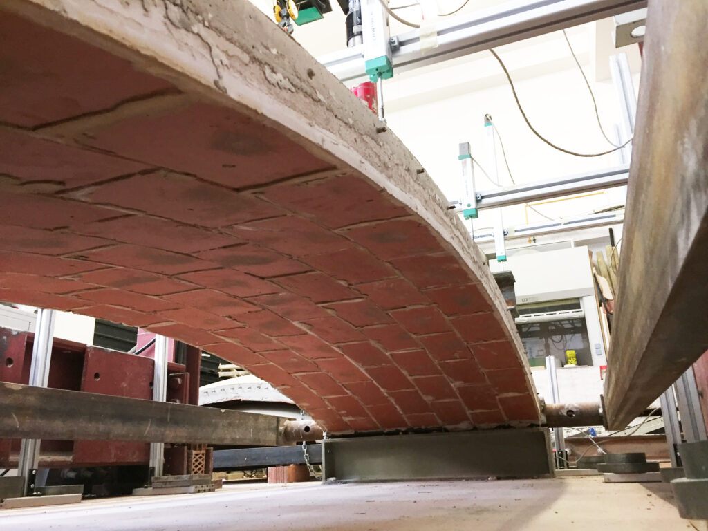
Experimental research, including load tests on material samples and full-scale prototypes, was carried out to validate the construction technique, being the first laboratory tests of this kind of composite structures [31] [32] (Figure 6). The calibration of finite element models based on the experimental results allowed the definition of a reliable modelling technique, material model and material properties for the analysis of this kind of structures. Additionally, a method based on limit analysis [33] was described to safely design such singly-curved structures and assess their strength and stability against external loading. The method was called Extended Limit Analysis of Reinforced Masonry (ELARM), started by Roca et al. [34] and provides graphical and intuitive results in 2D [30]. A three-dimensional approach of ELARM was presented as well [35].
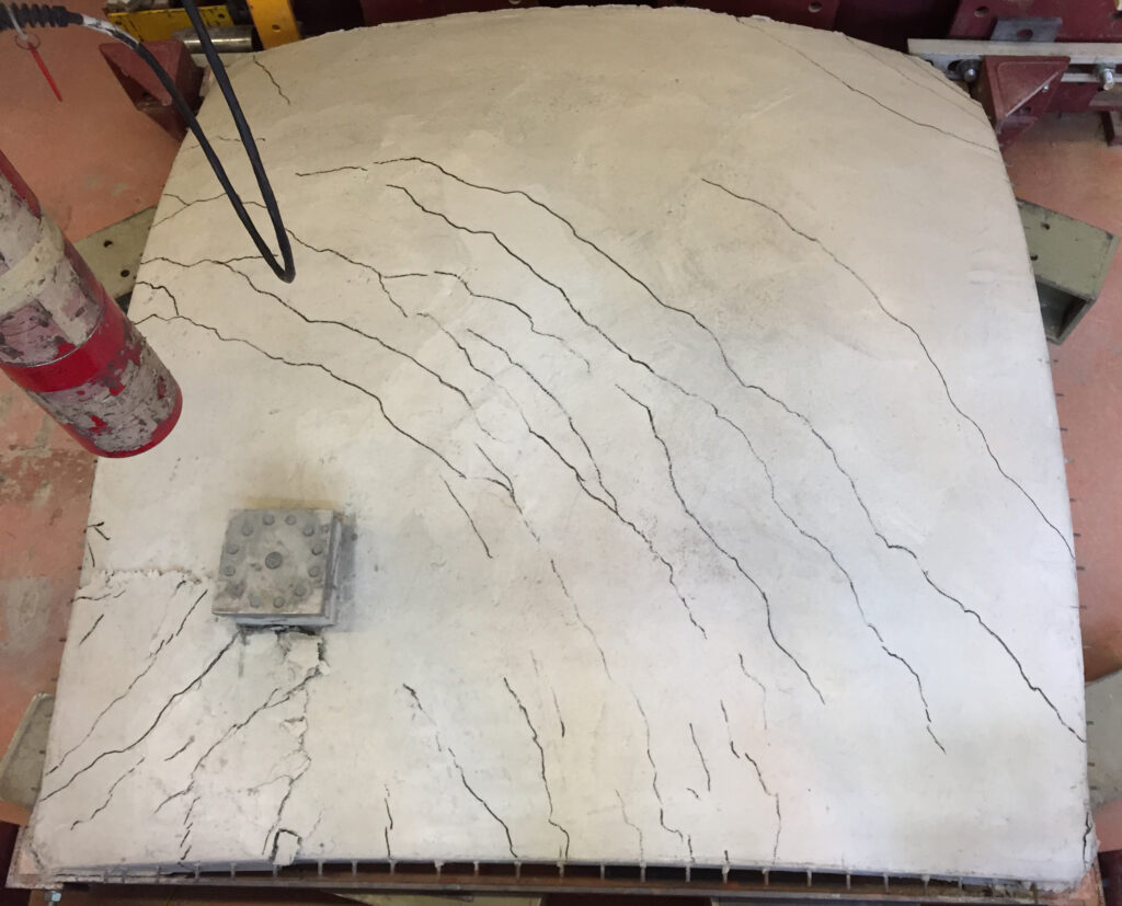
Structural analysis, experimental research and design methods have been successfully provided for this construction technique. However, this is not enough to make it enter the construction mass market. The assessment of the technique’s viability is highly dependent on the shape, the span and the number of times this shape is repeated. Moreover, construction costs are variable and depend on many factors, the location being an important one. Regarding the main topic of this post, i.e., considering the use of the presented technique for small- or medium-span floor systems, it could be profitable and competitive in contexts where the construction labour force is not expensive.
Finding the balance between sustainability and economy in the fabrication of optimised floor slabs is one of the challenges of the third phase of the ETH-based National Centre of Competence in Research Digital Fabrication (NCCR dfab). On the one hand, researchers need to address sustainability focused on material and waste reduction, the use of materials with less carbon footprint, circular construction and reuse possibilities. On the other hand, economic systems should be created to allow the developed ideas, concepts and patents to get to the mass market to represent a fundamental change in the construction industry.
As mentioned above, solutions are context-dependent. Local resources, materials, traditions and know-how make a system succeed or fail in different parts of the world. Therefore, to achieve a relevant, global environmental impact, special attention should be paid to the implementation of innovations where extensive construction will happen in the following decades.
*In this post, the term “formwork” in parts also refers to the elements supporting the formwork in the sense of “falsework”.
[1] Block P, Van Mele T, Rippmann M, Ranaudo F, Calvo Barentin C, Paulson N. Redefining Structural Art: Strategies, necessities and opportunities. The Structural Engineer 2020;98:66–72.
[2] Mai I, Brohmann L, Freund N, Gantner S, Kloft H, Lowke D, et al. Large Particle 3D Concrete Printing—A Green and Viable Solution. Materials 2021;14:6125. https://doi.org/10.3390/ma14206125.
[3] Agustí-Juan I, Habert G. Environmental design guidelines for digital fabrication. Journal of Cleaner Production 2017;142:2780–91. https://doi.org/10.1016/j.jclepro.2016.10.190.
[4] Bischof P, Mata-Falcón J, Kaufmann W. Fostering innovative and sustainable mass-market construction using digital fabrication with concrete. Cement and Concrete Research 2022;161:106948. https://doi.org/10.1016/j.cemconres.2022.106948.
[5] Hawkins W, Orr J, Shepherd P, Ibell T. Design, Construction and Testing of a Low Carbon Thin-Shell Concrete Flooring System. Structures 2019;18:60–71. https://doi.org/10.1016/j.istruc.2018.10.006.
[6] Hawkins W, Orr J, Ibell T, Shepherd P. A design methodology to reduce the embodied carbon of concrete buildings using thin-shell floors. Engineering Structures 2020;207:110195. https://doi.org/10.1016/j.engstruct.2020.110195.
[7] Mata-Falcón J, Bischof P, Huber T, Anton A, Burger J, Ranaudo F, et al. Digitally fabricated ribbed concrete floor slabs: a sustainable solution for construction. RILEM Tech Lett 2022;7:68–78. https://doi.org/10.21809/rilemtechlett.2022.161.
[8] Burger J, Huber T, Mata-Falcón J, Lloret Fritschi E, Kaufmann W, Gramazio F, et al. Design, fabrication, and testing of an optimised reinforced concrete floor slab fabricated with robotically 3D printed formwork (accepted). Third RILEM International Conference on Concrete and Digital Fabrication, 2022.
[9] López López D, Veenendaal D, Akbarzadeh M, Block P. Prototype of an ultra-thin, concrete vaulted floor system. Proceedings of IASS Annual Symposia 2014;2014:1–8.
[10] Liew A, López López D, Van Mele T, Block P. Design, fabrication and testing of a prototype, thin-vaulted, unreinforced concrete floor. Engineering Structures 2017;137:323–35. https://doi.org/10.1016/j.engstruct.2017.01.075.
[11] Nuh M, Oval R, Orr J, Shepherd P. Digital fabrication of ribbed concrete shells using automated robotic concrete spraying. Additive Manufacturing 2022:103159. https://doi.org/10.1016/j.addma.2022.103159.
[12] Ochsendorf J. Guastavino Vaulting: The Art of Structural Tile. Reprint edition. New York: Princeton Architectural Press; 2013.
[13] Truñó A. Construcción de bóvedas tabicadas. 1st edition. Madrid: INSTITUTO JUAN DE HERRERA; 2004.
[14] López López D, Domènech Rodríguez M, Palumbo Fernández M. “Brick-topia”, the thin-tile vaulted pavilion. Case Studies in Structural Engineering 2014;2:33–40. https://doi.org/10.1016/j.csse.2014.09.001.
[15] López López D, Van Mele T, Block P. Tile vaulting in the 21st century. Informes de la Construcción 2016;68:e162–e162. https://doi.org/10.3989/ic.15.169.m15.
[16] Torroja Miret E. The structures of Eduardo Torroja: an autobiography of engineering accomplishment. New York: F.W. Dodge Corporation; 1958.
[17] Torroja Miret E. Memoria. No 19.301 1926.
[18] Torroja Miret E. Iglesia de Pont de Suert. Informes de la Construcción 1962;14:59–70. https://doi.org/10.3989/ic.1962.v14.i137.4933.
[19] López López D, Van Mele T, Block P. The combination of tile vaults with reinforcement and concrete. International Journal of Architectural Heritage 2019;13:782–98. https://doi.org/10.1080/15583058.2018.1476606.
[20] Halpern AB, Billington DP, Adriaenssens S. The Ribbed Floor Slab Systems of Pier Luigi Nervi n.d.:7.
[21] Anderson S. Eladio Dieste: Innovation in Structural Art. 1st edition. New York: Princeton Architectural Press; 2004.
[22] Dieste E, Arana M, Garabelli L. Diálogos con Dieste. SUMMA 1980;8:96–101.
[23] López López D, Van Mele T, Block P. Dieste, González Zuleta and Sánchez del Río: Three approaches to reinforced-brick shell structures. Structural Analysis of Historical Constructions: Anamnesis, Diagnosis, Therapy, Controls, CRC Press; 2016.
[24] Dieste E. Iglesia en Montevideo. Templo parroquial de Atlántida. Informes de la Construcción 1961;13:43–56. https://doi.org/10.3989/ic.1961.v13.i127.5106.
[25] Cassinello P, Schlaich M, Torroja JA. Félix Candela. In memorian (1910-1997). From thin concrete shells to the 21st century’s lightweight structures. Informes de la Construcción 2010;62:5–26. https://doi.org/10.3989/ic.10.040.
[26] González Moreno-Navarro JL, Casals Balagué A. Gaudí y la razón constructiva. Un legado inagotable. Akal; 2002.
[27] Moya Blanco L, Domínguez Salazar JA. Capilla del Colegio de Santa María del Pilar, Madrid. Informes de la Construcción 1965;18:49–61. https://doi.org/10.3989/ic.1965.v18.i173.4340.
[28] Moya Blanco L. Memoria descriptiva de construcción y material y mediciones del proyecto para la construcción de una capilla y cripta en el colegio Santa María del Pilar 1963.
[29] López López D. Tile Vaults as Integrated Formwork for Concrete Shells: Construction, Experimental Testing, Structural Analysis and Design. Doctoral Thesis. ETH Zurich, 2019. https://doi.org/10.3929/ethz-b-000417993.
[30] López López D, Roca P, Liew A, Van Mele T, Block P. Tile vaults as integrated formwork for reinforced concrete: Construction, experimental testing and a method for the design and analysis of two-dimensional structures. Engineering Structures 2019;188:233–48. https://doi.org/10.1016/j.engstruct.2019.03.034.
[31] López López D, Bernat-Maso E, Gil L, Roca P. Experimental testing of a composite structural system using tile vaults as integrated formwork for reinforced concrete. Construction and Building Materials 2021;300:123974. https://doi.org/10.1016/j.conbuildmat.2021.123974.
[32] López López D, Bernat-Maso E, Gil L, Roca P. Experimental testing of tile vaults. Brick and Block Masonry – From Historical to Sustainable Masonry, CRC Press; 2020.
[33] Heyman J. The stone skeleton. International Journal of Solids and Structures 1966;2:249–79.
[34] Roca P, López-Almansa F, Miquel J, Hanganu A. Limit analysis of reinforced masonry vaults. Engineering Structures 2007;29:431–9. https://doi.org/10.1016/j.engstruct.2006.05.009.
[35] López López D, Roca P, Liew A, Méndez Echenagucia T, Van Mele T, Block P. A three-dimensional approach to the Extended Limit Analysis of Reinforced Masonry. Structures 2022;35:1062–77. https://doi.org/10.1016/j.istruc.2021.06.013.
David López López
Comment on this post on LinkedIn or Instagram
Link zur deutschen Version: Die Finite-Elemente-Methode im konstruktiven Ingenieurbau
Basic principles and areas of application of the FEM
In the last decades, computer-aided calculation methods – particularly the Finite-Element-Method (FEM) – have become an indispensable tool in engineering. With the development of the FEM, everyday calculations and routine tasks can be automated and carried out without careless mistakes. Thus (at least a part) of Konrad Zuse’s [1] dream of taking over “annoying” tasks by a fully automated calculating machine has become a reality. The engineer’s task has shifted from calculation to modelling and the interpretation of results, for which, however, the underlying theories and methods should be applied consciously and correctly. This has not made the art of structural analysis superfluous, but it has made it more demanding and exciting.
In general, the FEM provides a numerical approximation for all tasks that can be represented mathematically with partial differential equations, for which no closed solutions are available. More simply, complex systems (load-bearing structures) are divided into components (finite elements) and mathematically linked to form an overall model. If the mechanical properties (stiffness) of the individual elements are known through a relationship between stresses and strains specified within the framework of the selected mechanical model, the effects (e.g. internal forces) on the overall model can be determined under the given actions together with the boundary conditions (support conditions).
For the everyday tasks of a structural engineer, the linear-elastic FEM is mostly used, whereby a linear relationship between the stresses and strains is assumed. The FEM supplies e.g. the internal forces for the dimensioning of structures using ideal-plastic models. In exceptional cases, e.g. for the static verification of existing structures, the nonlinear [2] FEM is used more and more often. A nonlinear relationship between the stresses and strains is then applied, which allows the analysis of the load-deformation behaviour, the cracking behaviour and the associated redistribution of internal forces. In contrast to conventional calculation methods, this allows to identify load-bearing reserves, with which more efficient and resource-saving structures can be built or, ideally, expensive strengthenings can be avoided during a static verification of existing structures. While the pure application of such nonlinear FEM programs is relatively easy nowadays, thanks to user-friendly interfaces, choosing the appropriate (nonlinear) material and structural model for a given problem becomes more complex. The model ideas and their limitations, as well as the peculiarities of an NLFE calculation (e.g. divergences) should be understood in detail. Imparting this knowledge is a central challenge for us as a teaching and research institute.
Historical outline of the FEM
In general, the development of FEM does not go back to a single person or a single field but has a strong interdisciplinary character with aspects from mathematics, mechanics, engineering and computer science. The development of the FEM began in the 1950s and was pioneered by J. Argyris at the Technical University of Stuttgart, R.L. Taylor or R. Clough at the University of California, Berkely and O.C. Zienkiewicz at the University of Wales (all qualified civil engineers!). From the 1960s, the development picked up speed with the first international FEM conference in 1965 and the first standard book by Zienkiewicz in 1967 entitled “The Finite Element Method in Structural and Continuum Mechanics”.
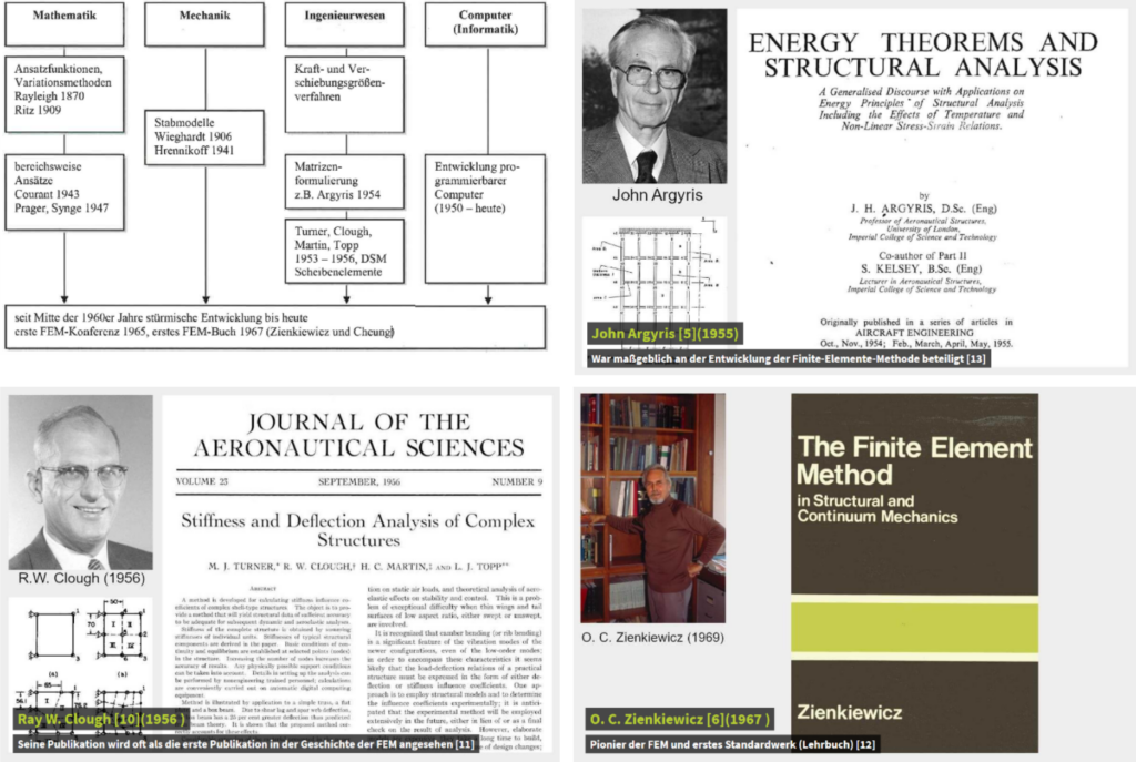
The application of the FEM to reinforced concrete structures began in the late 1960s with the work of Ngeo and Scordelis 1967 and Rashid 1968. Since then, countless publications and books have been published with the theoretical basics, use cases and guidelines (see FIB bulletin 45 2008). The first FEM-software were developed at universities and developed into commercial FEM packages with increased user-friendliness after 1970. This resulted in a large number of different software, including different types of elements and various mathematical solution algorithms for the spatial and temporal discretisation of the given problem. D. Mitchel, M.P. Collins and F.J. Vecchio from the University of Toronto played a pioneering role in developing nonlinear material models for reinforced concrete in the 1980s (development of compression field theories and their implementation in the FEM-software VecTor). Today, the FEM is one of the most widely used numerical solution methods for various physical tasks in all engineering sciences up to weather forecasts. We can be all the more proud that civil engineers made a significant contribution to the development of the FEM.
NLFE-tools at the Chair of Concrete Structures and Bridge Design
At the Chair of Concrete Structures and Bridge Design, we concentrate on developing nonlinear material models and their implementation in numerical methods, such as FEM. In recent years, various tools for nonlinear finite element analysis of reinforced concrete and masonry structures have been developed:
The Compatible Stress Field Method (CSFM) is suitable for analysing reinforced concrete under a plane stress state (e.g. frame corners or longitudinal beams of a box girder bridge, as shown in Figure 3). The CSFM is based mainly on the implementation of the tension chord model in the FEM-software Idea StatiCa Detail.
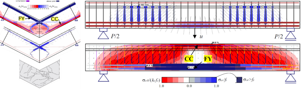
The CMM-Usermat contains the implementation of the Cracked Membrane Model (developed by Prof. Dr. Walter Kaufmann) as a user-defined material (Usermat) in the FEM program Ansys Mechanical APDL. Combined with a layer model, shell structures made of reinforced concrete can be analysed (see Figure 4).
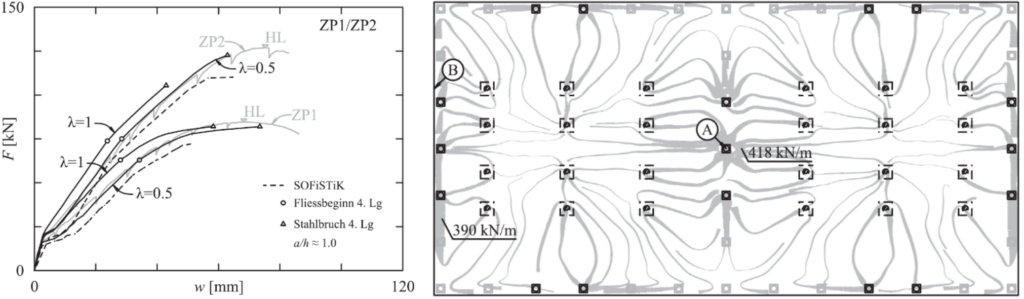
The URM-Usermat can be used to analyse the nonlinear load-bearing behaviour of unreinforced masonry structures (see Figure 5). The URM-Usermat is based on an implementation of extended failure criteria by Ganz (which were developed in the 1980s at the ETH Zurich and are still used today as the basis for masonry design) as user-defined material in the FEM program Ansys Mechanical APDL. In combination with the CMM-Usermat, the complex load-bearing behaviour of mixed structures made of reinforced concrete and masonry can be examined (see Figure 6).
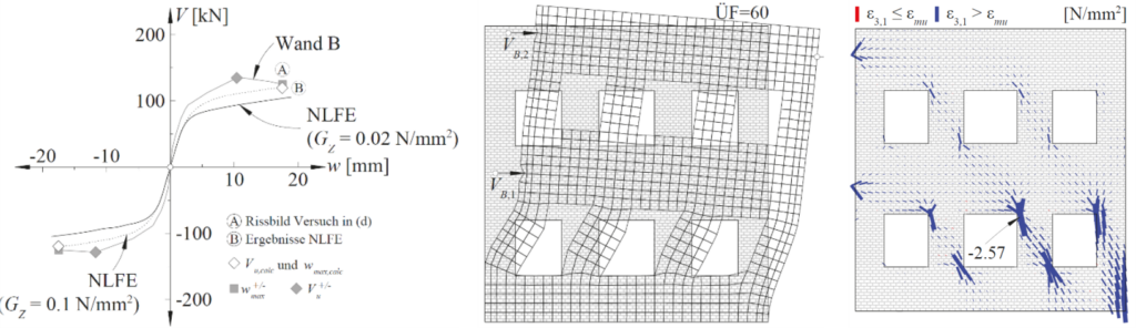
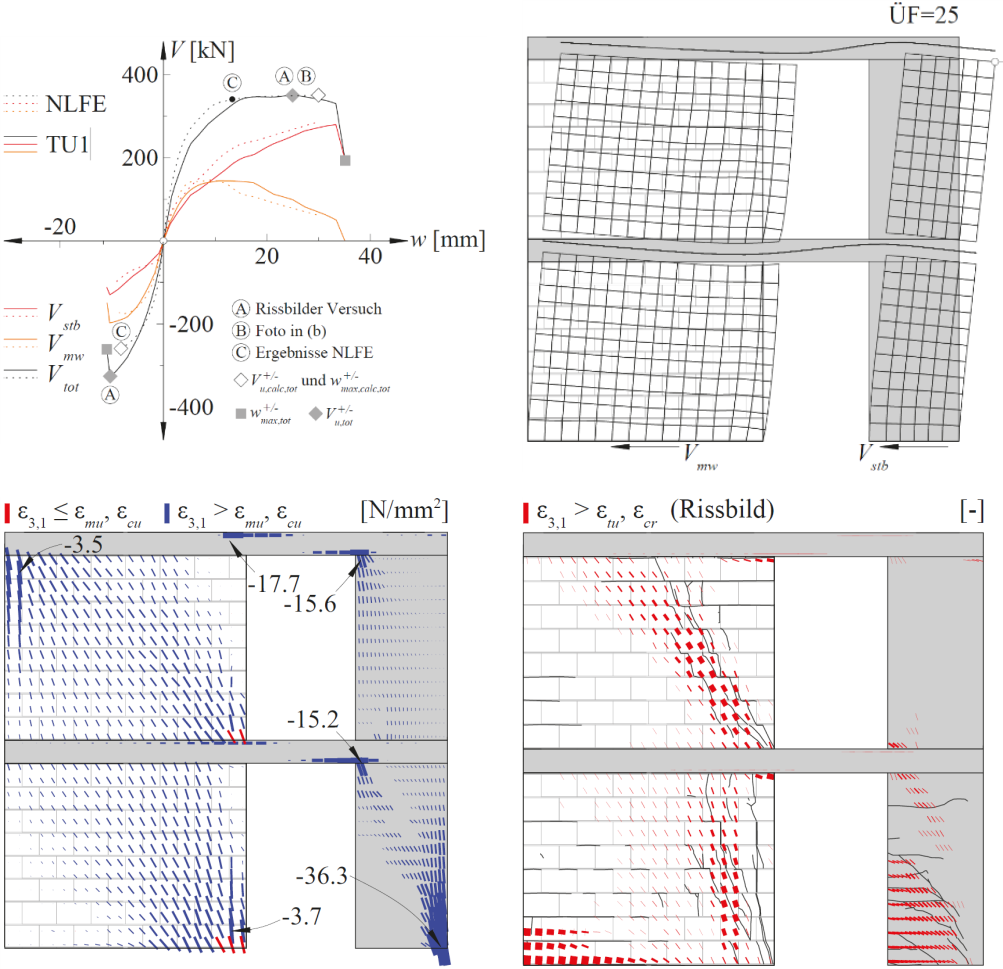
All NLFE-tools have in common that the material models take into account the relevant properties of the load-bearing behaviour based on mechanically consistent relationships. In addition, only a few physically clearly defined input parameters are required, which are known in the design or assessment phase. This makes the NLFE-tools ideal for use in construction practice.
Future developments
The NLFE-tools are currently being implemented in the StrucEng Library, which is being developed at the Professorship for Concrete Structures and Bridge Design. The StrucEng Library is an open-source software that enables computer-aided calculations of load-bearing structures made of reinforced concrete and masonry. In addition to the nonlinear material models, various other material models are available, which cover the entire spectrum from structural design to analysis with linear-elastic ideal-plastic models. In the future, the StrucEng Library will be available in open-source format, which means that practical engineers can freely use the corresponding model using a user-friendly interface. In addition, the nonlinear material models are being further developed in various projects (e.g. corrosion, fibre-reinforced concrete, etc.). In the future, courses in the numerical modelling of reinforced concrete and masonry structures will also be offered at our Chair. With this special focus on numerical modelling in teaching and research, we are convinced that the prospective civil engineers will be fit for future challenges.
[1] Konrad Ernst Otto Zuse was a German civil engineer (!), inventor and entrepreneur. With his development of the Z3 in 1941, Zuse built the world's first working computer.
[2] In the context of these blog posts, nonlinearity always means material nonlinearity. There are also geometric nonlinearities (second-order calculations), which are taken into account via the P-Delta effect.
Marius Weber
Comment on this post on LinkedIn or Instagram
Link zur deutschen Version: Langzeiteinflüsse bei der Bemessung von monolithisch verbundenen Pfeilern für vorgespannte Träger oder Platten
This blog post is about a technically challenging topic: how to consider long-term effects (shrinkage and creep) in the design of piers monolithically connected to a prestressed girder or slab. This structural arrangement can be found in monolithic building structures or, more commonly, in prestressed concrete bridges. Therefore, I do not doubt that this will be a topic of great interest if you are passionate about structural design and perhaps even had to deal with it already in your professional practice.
The design of monolithic, i.e., jointless structures is becoming increasingly common in bridge design in Europe. The main reasons for this are, firstly, the desire to eliminate durability problems and reduce maintenance costs, and secondly, that guidelines for the design of such structures are becoming increasingly available. Switzerland is a reference country that has contributed to developing this type of structures, where traditionally, concrete bridges with piers monolithically connected to the deck, and semi-integral or integral bridges (monolithic connection at both abutments) [1] where possible, are preferred [2]. Numerous realisations of jointless bridges [3][4][5][6][7] have been built in Switzerland, and technical guidelines promote integral or semi-integral bridges [1][2] (old reference1Routes Nationales Suisses, Projects Standards de Ponts, Passage Supérieur avec Béquilles en V en Béton Coule sur Place, Departement Federak de L’Interieur, Bern 1972 from the 70s). Given the resulting tendency to build ever longer monolithic jointless bridges, increasingly more accurate and complex calculations are required to reliably design the piers. About a decade ago, I had the chance to contribute to a publication supporting engineers in the design of piers of long jointless concrete structures [8], but that document is limited to building structures, where the slab or girder is not prestressed.
Despite the availability of powerful structural analysis software, analysing statically indeterminate structures subjected to long-term effects remains a challenge. A clear example of this, which we will discuss in this blog, is how to estimate the bending moments due to long-term effects in a concrete pier monolithically connected to a prestressed girder. In this type of structure, a large part of the forces acting in the pier is associated with the deformations imposed to the pier head by the deck, which are relevant in Serviceability Limit States (SLS) and Ultimate Limit States (ULS STR and ULS FAT2Although the imposed deformations (shrinkage and creep) are no cyclic actions, they are relevant in ULS FAT (fatigue failure) for concrete fatigue verifications, which depend on the absolute maximum and minimum concrete stresses.). However, obtaining the internal forces in the pier caused by long-term effects with acceptable accuracy is complex since the stresses vary non-linearly over time (the modulus of elasticity varies with the age of the concrete), the girder and the pier do not creep equally (different creep coefficient, i.e. different concretes and of different ages), and the cracked bending stiffness varies over the pier height and depends on the load history (maximum tensile stress). Thus, in normal engineering practice, to easily estimate the internal forces in the piers, engineers typically consider: (i) reduced pier bending stiffnesses due to cracking (generally constant or linearly variable along the piers), which are calculated by iteration and are different for SLS, ULS STR and ULS FAT verifications, (ii) about 40…50% of the total shrinkage of the deck at infinite time to take into account the long-term effects, but (iii) neglect long-term effects due to prestressing arguing that creep of the pier compensates the increase of the pier head displacement due to creep of the girder.
The first simplification, if done with due engineering judgement, can generally be accepted, but should be complemented by a sensitivity study to cover the uncertainties of the calculations. However, with respect to the second and third simplifications, the following questions inevitably arise: Is this approach appropriate and under what conditions is it valid? What is the background behind it? Is this conservative? Is it necessary to perform a sensitivity analysis to cover uncertainties if this action is decisive for the design?
After this introduction, it is time to answer these questions. In the following, you and I (let me involve you in the analysis) will analytically solve the formulated problem, interpret the results and draw some conclusions. The structure to be analysed is shown, in a simplified manner, in Figure 1. The horizontal element represents a prestressed concrete girder, and the vertical one a pier of height h, which is monolithically connected to the girder at a distance LT (expansion length) from the fixed point. The mechanical properties are constant for both elements and are indicated in Figure 1(a). Figure 1(b) and Figure 1(c) show the horizontal displacements of the pier head over time, uh,εcs(t) and uh,P,el(t), caused by the shrinkage εcs(t) and the prestressing P(t) of the girder, respectively. Note that the restraint of the pier to the horizontal displacements imposed by the girder is neglected since, in general, the axial stiffness of the girder is orders of magnitude much higher than the horizontal (bending) stiffness of the pier. Furthermore, according to the equations presented in Figure 1(c), the following assumptions have been made: normal force constant along the girder (no frictional prestress losses) and EPIP<<EGIG, i.e., pier “perfectly” double-clamped. Note that the latter consideration is not suitable for some cases, e.g. building structures where the bending stiffness of the column is not negligible compared to that of the girder or flexible foundations (deep foundations). However, the long-term effects calculated below are formulated independently of the pier and deck stiffnesses, which can be included directly as imposed deformations in finite element analysis (FEA). In addition, the influence of the pier creep on the corresponding (uncracked and cracked) bending stiffness is not accounted into the following calculations, thus, the equivalent reduced bending stiffness of the pier, considering creep and cracking, should be used in the static system.
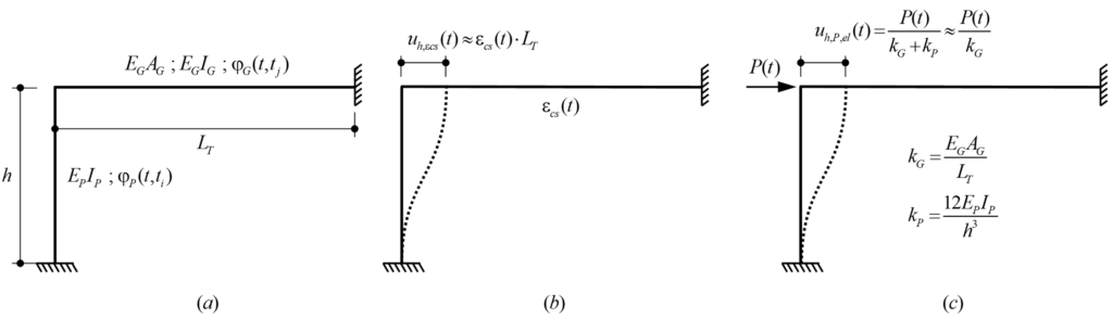
EG: Modulus of elasticity of the girder
EP: Modulus of elasticity of the pier
IG: Second moment of area (area moment of inertia) of the girder
IP: Second moment of area (area moment of inertia) of the pier
φG(t,tj): Creep coefficient of the girder
φP(t,ti): Creep coefficient of the pier
In order to solve the system analytically, the frame structure in Figure 1 is simplified according to Figure 2. To obtain the internal forces in the pier caused by the imposed horizontal displacement uh, the isolated double-clamped pier of height h (Figure 2 (a)) can be replaced by the isolated hinge-clamped pier of height h/2 (Figure 2 (b)). Thus, Figure 2(c) shows the equivalent simplified system to obtain the internal forces in the pier due to a horizontal displacement u’h at the pier head, which is equal to half of the horizontal displacement uh in the original system (Figure 1), i.e. u’h (t)= uh(t)/2. Note that in order to achieve the correct pier head displacement caused by prestressing, the equivalent prestressing force P’ (t) in the simplified system (Figure 2(c)) is equal to half of the prestressing force P(t)/2 in the original system (Figure 1) if the bending stiffness of the pier is neglected to the axial stiffness of the girder, otherwise, it is as follows:

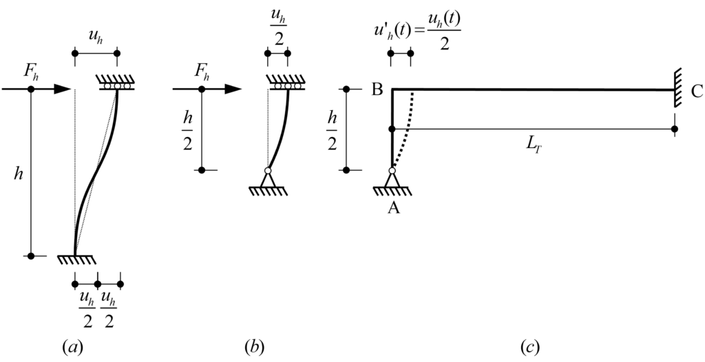
In the following, we isolate the pier of the simplified system shown in Figure 2(c) and solve a system composed of a pier with a single degree of static indeterminacy by using the time dependent force method and formulating the compatibility equations over time, where:
BS (basic system): Fixed rotation in B (pier head) released
RV (redundant variable): Bending moment in B (pier head)
In addition, the time-dependent bending moments at the pier head due to shrinkage and prestressing are calculated separately.
Time-dependent behaviour of concrete pier
1. Shrinkage (time-dependent pier head displacement3Note that the pier head displacements can be treated analogously as settlements in our long-term effects lecture (time-independent or time-dependent).)
Figure 3 shows the isolated pier with the basic system (BS) and the redundant variable (RV) used to determine the bending moment MB(t) by using the force method. Since the bending moment MB(t) varies over time, compatibility at Support B is expressed both at the initial time as well as time-dependent.
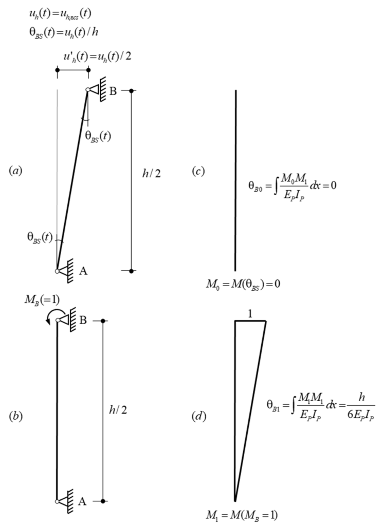
The shrinkage εcs(t) of the girder causes an imposed deformation over time, which generates horizontal displacements uh(t) and bending moments MB(t) at the pier head. At the initial time, the horizontal displacement uh(t0) and the bending moment MB(t0) are both zero (no shrinkage). At any given time t> t0, the girder has shrunk by εcs(t), causing a horizontal displacement uh(t) and the bending moment MB(t), see Figure 4(a) and Figure 4(b) respectively. Assuming that the shrinkage of the girder, and hence, the imposed deformations over time uh(t) are proportional to the creep function of the pier, uh(t) can be expressed as:
![\[{{u}_{h}}(t)={{u}_{h,\infty }}\frac{{{\varphi }_{P}}(t,{{t}_{i}})}{{{\varphi }_{P}}(\infty ,{{t}_{i}})}\text{ (eq}\text{. 1)}\]](https://concrete.ethz.ch/wp-content/ql-cache/quicklatex.com-1533735f2c8fccbff81d0ea338d639e6_l3.png "Rendered by QuickLaTeX.com")
Hence, at infinite time, the horizontal displacement at the pier head reaches the maximum horizontal displacement uh,∞ = εcs,∞·LT (Figure 4(a)). However, as we will see below, the bending moment MB,∞ (t=∞) will be lower than the elastic bending moment MB,el,∞ caused by the maximum horizontal displacement uh,∞ (Figure 4(b)).
The bending moment MB(t) at the pier head can be formulated as follows:
![\[{{M}_{B}}(t)=\cancel{{{M}_{B}}({{t}_{0}})}+\Delta {{M}_{B}}(t)=\Delta {{M}_{B}}(t)\text{ (eq}\text{. 2)}\]](https://concrete.ethz.ch/wp-content/ql-cache/quicklatex.com-a49ed75a91cf83e02d6313b703191b89_l3.png "Rendered by QuickLaTeX.com")
Where ΔMB(t) is the bending moment increment over time due to shrinkage.
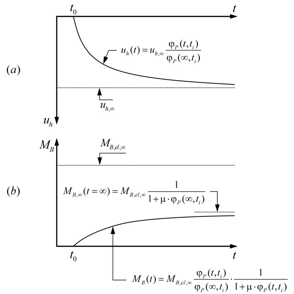
Rotation compatibility condition at the initial time t=t0:
Rotation compatibility at the initial time (note that all actions are applied in the basic system (BS)) yields the expression:
![\[{{\theta }_{B}}({{t}_{0}})=\cancel{{{\theta }_{B0}}}+{{M}_{B}}({{t}_{0}})\cdot {{\theta }_{B1}}={{\theta }_{BS}}({{t}_{0}})=0\to {{M}_{B}}({{t}_{0}})=\frac{\cancel{{{\theta }_{BS}}({{t}_{0}})}}{{{\theta }_{B1}}}=0\text{ (eq}\text{. 3)}\]](https://concrete.ethz.ch/wp-content/ql-cache/quicklatex.com-e03f6a33aec51bc4ef804d72502dde5b_l3.png "Rendered by QuickLaTeX.com")
As mentioned above, it is evident that at the initial time, the bending moment at the pier head is zero MB(t0) = 0 since shrinkage has not started yet.
Time-dependent rotation compatibility condition (Trost’s method):
The development of the time-dependent rotation compatibility is performed by using Trost’s method. I recommend our long-term effects lecture on Advanced Structural Concrete if you are not familiar with this method.
![\begin{align*}& {{\theta }_{B}}(t)=\cancel{{{\theta }_{B0}}}\left[ 1+{{\varphi }_{P}}(t,{{t}_{i}}) \right]+\cancel{{{M}_{B}}({{t}_{0}})}\cdot {{\theta }_{B1}}\left[ 1+{{\varphi }_{P}}(t,{{t}_{i}}) \right]+\Delta {{M}_{B}}(t)\cdot {{\theta }_{B1}}\left[ 1+\mu \cdot {{\varphi }_{P}}(t,{{t}_{i}}) \right]={{\theta }_{BS}}(t)\text{ (eq. 4)} \\& {{\theta }_{BS}}(t)={{\theta }_{BS,\infty }}\frac{{{\varphi }_{P}}(t,{{t}_{i}})}{{{\varphi }_{P}}(\infty ,{{t}_{i}})} \\& \Delta {{M}_{B}}(t)={{M}_{B}}(t)=\frac{{{\theta }_{BS,\infty }}}{{{\theta }_{B1}}}\cdot \frac{{{\varphi }_{P}}(t,{{t}_{i}})}{{{\varphi }_{P}}(\infty ,{{t}_{i}})}\cdot \frac{1}{1+\mu \cdot {{\varphi }_{P}}(t,{{t}_{i}})} \\& {{M}_{B,el,\infty }}=\frac{{{\theta }_{BS,\infty }}}{{{\theta }_{B1}}}=\frac{6{{E}_{P}}{{I}_{P}}}{{{h}^{2}}}{{\varepsilon }_{cs,\infty }}{{L}_{T}}\text{ (eq}\text{. 5)} \\& {{M}_{B}}(t)={{M}_{B,el,\infty }}\cdot \frac{{{\varphi }_{P}}(t,{{t}_{i}})}{{{\varphi }_{P}}(\infty ,{{t}_{i}})}\cdot \frac{1}{1+\mu \cdot {{\varphi }_{P}}(t,{{t}_{i}})}\text{ (eq}\text{. 6)} \\& {{M}_{B,\infty }}(t=\infty )={{M}_{B,el,\infty }}\frac{1}{1+\mu \cdot {{\varphi }_{P}}(\infty ,{{t}_{i}})}\text{ (eq}\text{. 7)} \\\end{align*}](https://concrete.ethz.ch/wp-content/ql-cache/quicklatex.com-c9fd5efc3d38b9995908d55c0a57a3af_l3.png "Rendered by QuickLaTeX.com")
Note that the compatibility equation (4) expresses that the rotation θB(t) caused by the bending moment MB(t) (redundant variable RV) must compensate the rotation due to the pier head displacement θBS(t); both rotations are determined in the basic system. In other words, the total rotation of the pier head B has to be zero (see Figure 3). The ageing coefficient μ4Ageing coefficient μ could be obtained by solving a linear and inhomogeneous Volterra integral equation, but for typical cases, one may assume μ ≈ 0.8, introduced by Trost, accounts for the fact that concrete creeps less under loads applied at a later point in time. From this condition, the bending moment MB(t) can be determined at any time t (eq. 6) and expressed in terms of the elastic bending moment MB,el,∞ (eq. 5).
2. Prestressing
Unlike shrinkage, where the horizontal displacement at the pier head increases from zero at the initial time, prestressing is an instantaneous action at the initial time (t=t0), which causes an initial horizontal displacement uh(t0) = uh,P,el(t0) and a corresponding initial elastic bending moment MB(t0) = MB,el(t0) at the pier head. Afterwards, both the horizontal displacement uh(t) and the bending moment MB(t) vary over time. Similar to the calculation of the bending moments due to shrinkage, the pier is isolated and the basic system (BS) with the bending moment at the pier head B MB(t) as redundant variable is used, see Figure 5.
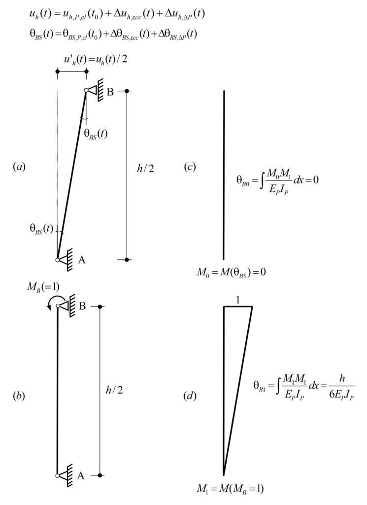
The total horizontal displacement at the pier head uh(t) due to prestressing amounts to:
![\[{{u}_{h}}(t)={{u}_{h,P,el}}({{t}_{0}})+\Delta {{u}_{h,\varepsilon cc}}(t)+\Delta {{u}_{h,\Delta P}}(t)\text{ (eq}\text{. 8)}\]](https://concrete.ethz.ch/wp-content/ql-cache/quicklatex.com-4b3a1f6a74f7064fc20686c4efa2b043_l3.png "Rendered by QuickLaTeX.com")
where,
uh,P,el(t0) is the initial horizontal displacement at the pier head due to the elastic deformation of the girder caused by the initial prestressing force P(t0), i.e.,
![\[{{u}_{h,P,el}}({{t}_{0}})=\frac{P({{t}_{0}})}{{{k}_{G}}}\text{ (time-independent pier head displacement) (eq}\text{. 9)}\]](https://concrete.ethz.ch/wp-content/ql-cache/quicklatex.com-804594727fa224a2d921fee5bdf93b25_l3.png "Rendered by QuickLaTeX.com")
Δuh,ecc(t) is the horizontal displacement increment at the pier head over time due to long-term effects caused by the creep of the girder φG(t,tj).
![\[\Delta {{u}_{h,\varepsilon cc}}(t)={{\varphi }_{G}}(t,{{t}_{j}})\cdot {{u}_{h,P,el}}({{t}_{0}}\text{) (time-dependent pier head displacement) (eq}\text{. 10)}\]](https://concrete.ethz.ch/wp-content/ql-cache/quicklatex.com-84174135d01540df0084cdd33a2c48f9_l3.png "Rendered by QuickLaTeX.com")
Δuh,DP(t) is the horizontal displacement increment at the pier head over time due to the change of the prestressing force ΔP(t) (prestressing losses) over time due to shrinkage, creep and relaxation. It is considered proportional to the initial horizontal displacement uh,P,el(t0) and has a negative value since ΔP(t) <0:
![\[\Delta {{u}_{h,\Delta P}}(t)=\frac{\Delta P(t)}{P({{t}_{0}})}\cdot {{u}_{h,P,el}}({{t}_{0}})\text{ (time-dependent pier head displacement) (eq}\text{. 11)}\]](https://concrete.ethz.ch/wp-content/ql-cache/quicklatex.com-65c1bf8e8418e0ce7256379e268b0251_l3.png "Rendered by QuickLaTeX.com")
When the prestressing force is applied at the initial time (t=t0), the pier head exhibits an initial horizontal elastic displacement uh,P,el(t0). Subsequently, the horizontal displacement increases over time due to the creep of the girder Δuh,ecc(t), which is partly compensated by the prestressing force decrease due to the prestressing losses Δuh,ΔP(t), see Figure 6(a). On the other hand, the bending moment MB,el(t0) at the pier head caused by the imposed horizontal displacement uh,P,el(t0), elastic deformation of the girder caused by prestressing, is reduced over time due to creep and the prestressing losses ΔP(t) of the pier (Figure 6(b)). The bending moment MB(t) can be expressed as follows:
![\[{{M}_{B}}(t)={{M}_{B,el}}({{t}_{0}})+\Delta {{M}_{B}}(t)\text{ (eq}\text{. 12)}\]](https://concrete.ethz.ch/wp-content/ql-cache/quicklatex.com-55a97bd69ced108af2fd134b99e77193_l3.png "Rendered by QuickLaTeX.com")
Where ΔMB(t) is the bending moment increment over time due to creep of pier and girder, as well as the prestressing losses.
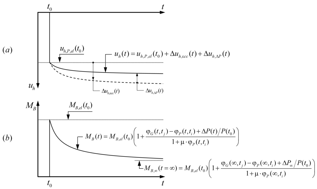
For calculating the bending moments MB(t) at the pier head over time, similar to calculations for shrinkage, we firstly apply the rotation compatibility at the initial time, and secondly, the time-dependent rotation compatibility using Trost’s method.
Rotation compatibility condition at the initial time t=t0:
Rotation compatibility in the basic system (BS) at the initial time (Figure 5) yields:

The initial bending moment MB(t0) at the pier head is equal to the initial elastic bending moment MB,el(t0), see eq. 14.
Time-dependent rotation compatibility condition (Trost’s method):
In the following, the equations are developed by using Trost’s method to determine the bending moment increment at the pier head over time ΔMB(t).
![\[{{\theta }_{B}}(t)={{\theta }_{B0}}\left[ 1+{{\varphi }_{P}}(t,{{t}_{i}}) \right]+{{M}_{B}}({{t}_{0}})\cdot {{\theta }_{B1}}\left[ 1+{{\varphi }_{P}}(t,{{t}_{i}}) \right]+\Delta {{M}_{B}}(t)\cdot {{\theta }_{B1}}\left[ 1+\mu \cdot {{\varphi }_{P}}(t,{{t}_{i}}) \right]={{\theta }_{BS,P,el}}({{t}_{0}})+\Delta {{\theta }_{BS,\varepsilon cc}}(t)+\Delta {{\theta }_{BS,\Delta P}}(t)\text{ (eq}\text{. 15)}\]](https://concrete.ethz.ch/wp-content/ql-cache/quicklatex.com-95e08604465bf578f7c2d9519c21a4f8_l3.png "Rendered by QuickLaTeX.com")
Note that the rotation at Support B θB(t) over time, analogous to the horizontal displacement, consists of:
![\[{{\theta }_{B}}(t)={{\theta }_{B,P,el}}({{t}_{0}})+\Delta {{\theta }_{B,\varepsilon cc}}(t)+\Delta {{\theta }_{B,\Delta P}}(t)\]](https://concrete.ethz.ch/wp-content/ql-cache/quicklatex.com-1ae664796905f139a2ab67077891e71c_l3.png "Rendered by QuickLaTeX.com")
where,

Substituting eq. 13 and eq. 14 in eq.15:
![\begin{align*} & {{\theta }_{B}}(t)={{M}_{B,el}}({{t}_{0}})\cdot {{\theta }_{B1}}\cdot {{\varphi }_{P}}(t,{{t}_{i}})+\Delta {{M}_{B}}(t)\cdot {{\theta }_{B1}}\left[ 1+\mu \cdot {{\varphi }_{P}}(t,{{t}_{i}}) \right]=\Delta {{\theta }_{BS,\varepsilon cc}}(t)+\Delta {{\theta }_{BS,\Delta P}}(t)\text{ (eq}\text{. 16)} \\ & \Delta {{M}_{B}}(t)=\left[ \frac{\Delta {{\theta }_{BS,\varepsilon cc}}(t)}{{{\theta }_{B1}}}+\frac{\Delta {{\theta }_{BS,\Delta P}}(t)}{{{\theta }_{B1}}}-{{M}_{B,el}}({{t}_{0}})\cdot {{\varphi }_{P}}(t,{{t}_{i}}) \right]\cdot \frac{1}{1+\mu \cdot {{\varphi }_{P}}(t,{{t}_{i}})}\text{ (eq}\text{. 17)} \\\end{align*}](https://concrete.ethz.ch/wp-content/ql-cache/quicklatex.com-7aebd9312fb06ce73977c40eccc9b7d6_l3.png "Rendered by QuickLaTeX.com")
On the other hand, the bending moment and the rotation at the pier head can be assumed to be proportional to the horizontal displacement over time. Therefore, from eq. 10 and eq. 11, we can formulate the bending moment increments ΔMB,εcc,el(t) and ΔMB,ΔP,el(t) due to creep and prestressing losses, respectively, as follows:

Substituting eq. 18 and eq. 19 in eq. 17:
![\[\Delta {{M}_{B}}(t)={{M}_{B,el}}({{t}_{0}})\cdot \frac{{{\varphi }_{G}}(t,{{t}_{j}})-{{\varphi }_{P}}(t,{{t}_{i}})+\frac{\Delta P(t)}{P({{t}_{0}})}}{1+\mu \cdot {{\varphi }_{P}}(t,{{t}_{i}})}\text{ (eq}\text{. 20)}\]](https://concrete.ethz.ch/wp-content/ql-cache/quicklatex.com-b75d1f9b09abd752031f43b8a4bcc97b_l3.png "Rendered by QuickLaTeX.com")
Finally, by substituting the bending moment increment ΔMB(t) from eq. 20 in eq. 12, the total bending moment at the pier head over time MB(t) is as follows:

3. Summary and discusion
Shrinkage:
The bending moment MB,∞ at the pier head at the infinite time due to shrinkage is as follows:
![\[{{M}_{B,\infty }}={{M}_{B,el,\infty }}\frac{1}{1+\mu \cdot {{\varphi }_{P}}(\infty ,{{t}_{i}})}\]](https://concrete.ethz.ch/wp-content/ql-cache/quicklatex.com-a37758496dd3dc3ef9adfe7890ce3986_l3.png "Rendered by QuickLaTeX.com")
Where μ ≈ 0.80 and ti, is the age of the pier concrete when the girder starts to shrink. Figure 7 shows the ratio of the bending moment MB,∞ to the elastic bending moment MB,el,∞ at the pier head at the infinite time as a function of the pier creep coefficient φP(∞,ti).
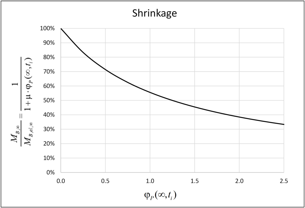
The bending moment MB(t) at the pier head due to shrinkage grows over time until it reaches a maximum bending moment MB,∞ at the infinite time (see Figure 4(b)), which is 1/(1+m·φjP(∞,ti)) times the elastic bending moment MB,el,∞ due to the short-term effect of the total shrinkage εcs,∞. The maximum bending moment MB,∞ at the pier head at the infinite time, which is independent of the girder creep coefficient φG(∞,ti), is equal to 38%·MB,el,∞ for a typical value of φP(∞,ti) = 2.0. This is the reason why many engineers consider 40% of the total shrinkage (40%·εcs,∞) to determine the internal forces in the piers at the infinite time due to long-term effects. However, since the piers are built ahead of the girder, the pier creep coefficient is often smaller than 2.0 at the concrete age when the girder starts to shrink, and anyway smaller in regions with high relative humidity (e.g. φP(∞,t0) ≈ 1.8 for C30/37 and RH ≈ 80% as common in Switzerland). Furthermore, if the beneficial effect of a cracked pier with correspondingly reduced stiffness is considered, an even lower equivalent creep coefficient jP (determined e.g. from a cross-sectional analysis, as the ratio of curvatures with and without creep) needs to be used. If the engineers do not have this background and use the reference of 40% (φP(∞,ti) = 2.0) indiscriminately, or even with a reduced value of shrinkage due to the high humidity, the design of the piers may be unsafe, particularly in SLS. For example, considering a pier creep coefficient at infinite time φP(∞,ti) = 1.25 from the time when the girder starts to shrink, the bending moment at the pier head is MB,∞ = 50%·MB,el,∞ , i.e. 32% higher than MB,∞ = 38%·MB,el,∞ for φP(∞,ti) = 2.0.
Prestressing:
The bending moment MB,∞ at the pier head at infinite time caused by prestressing (including short- and long-term effects) is:
![\[{{M}_{B,\infty }}={{M}_{B,el}}({{t}_{0}})\cdot \left( 1+\frac{{{\varphi }_{G}}(\infty ,{{t}_{j}})-{{\varphi }_{P}}(\infty ,{{t}_{i}})+\frac{\Delta {{P}_{\infty }}}{P({{t}_{0}})}}{1+\mu \cdot {{\varphi }_{P}}(\infty ,{{t}_{i}})} \right)\]](https://concrete.ethz.ch/wp-content/ql-cache/quicklatex.com-17534854d9d020a94b6d2381226cbdb9_l3.png "Rendered by QuickLaTeX.com")
where, tj and ti are the concrete age of the girder and pier, respectively, when the prestressing is applied.
Figure 8 shows the ratio of the bending moment increment ΔMB,∞ to the initial elastic bending moment MB,el(t0) at the pier head at the infinite time. Indeed, as often assumed in design, creep of the pier, together with the (negative) contribution of the prestressing losses, counteract and for specific values of the creep coefficients even compensate the increase of the pier head bending moments caused by creep of the girder. However, in typical cases, significant differences are observed. Generally, the ratio ΔMB,∞ / MB,el(t0) is a function of the pier creep coefficient φP(∞,ti), the girder creep coefficient φG(∞,tj), the prestressing losses ΔP∞/P(t0) and the coefficient m. The curves plotted in Figure 8 have been generated for μ=0.80, φG(∞,tj) = {1.0; 1.5; 2.0} and ΔP∞/P(t0)= {0%; 10%}. It is observed that the prestressing losses have a minor effect on the ratio ΔMB,∞ / MB,el(t0) (around 5% for the parameters used), which could be neglected in the calculations.
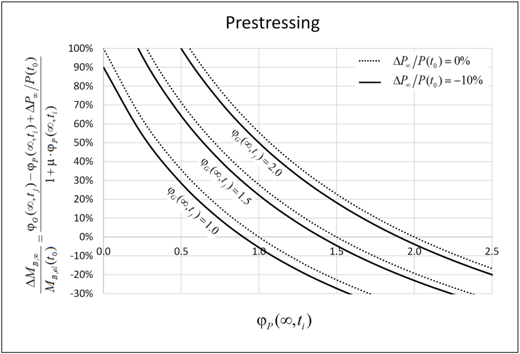
The ratio ΔMB,∞ / MB,el(t0) depends on the girder and pier creep coefficients (with ti and tj = concrete age of these elements when the prestressing is applied), and the prestressing losses. The initial bending moment MB,el(t0) at the pier head decreases over time if the pier creep coefficient φP(∞,ti) is higher than the girder creep coefficient φG(∞,tj), i.e. φP(∞,ti) > φG(∞,tj), but increases otherwise (neglecting prestressing losses), which typically applies since the piers are built ahead of the girder.
Considering a pier creep coefficient of φP(∞,ti) = 1.25, the bending moment increment ΔMB,∞ at infinite time increases by roughly 10% and 35% to the initial bending moment MB,el(t0) for girder creep coefficients of φG(∞,tj) = 1.5 and φG(∞,tj) = 2.0, respectively. An increase of 35% is not a priori negligible; however, it can be neglected for low and moderate prestressing levels of the girder since the bending moment increment ΔMB,∞ is usually small compared to the bending moment caused by shrinkage.
4. Conclusions
For a preliminary design (internal action estimation) of piers monolithically connected to a prestressed girder, it is a valid approximation to consider 40…50% of the total shrinkage at the infinite time εcs,∞ and neglect the incremental internal force over time due to prestressing. These considerations may also be acceptable in detailed design if the dimensioning of the piers is not decisive and the designer has control over the influence of the long-term effects on the structure, including its construction process. Generally, however, using a value of 40%·εcs,∞ indiscriminately to take into account the long-term effects may be unsafe side by underestimating the internal forces acting in the piers.
The equations presented for estimating the internal forces in the piers due to the long-term effects are useful in engineering practice. They allow a simple, yet considerably more accurate long-term analysis as required for long jointless structures with monolithic pier-girder connections. In addition, a proper strategy of casting stages can significantly help increase the lengths of jointless structures.
As a final remark, it is noted that while the moments at the pier heads caused by shrinkage and prestressing are reduced due to creep of the piers, the full girder displacements need to be accounted for when designing bearings and expansion joints and estimating bridge end displacements in integral abutments.
I hope this publication has been of interest and useful to you. Leave your comments.
Alejandro Giraldo Soto
Kommentieren Sie diesen Beitrag auf LinkedIn oder Instagram
Link zur deutschen Version: Duktilität und Rotationsvermögen im Stahlbetonbau
What is ductility? Why do we need it?
Ductility is a ubiquitous concept in structural engineering and structural concrete, the field treated specifically by this post.
In seismic engineering, some well-known authors have proposed definitions such as those given below.
Der Begriff Duktilität bezeichnet die Fähigkeit eines Tragelementes oder Tragwerks, sich nicht nur elastisch, sondern unter Aufrechterhaltung des Tragwiderstandes auch plastisch zu verformen.
(Paulay, Bachmann, Moser 1990 Erdbebenbemessung von Stahlbetonhochbauten)
The term “ductility” in structural design is used to mean the ability of a structure to undergo large deformations in the postelastic range without a substantial reduction in strength.
(Park 1991 Ductility of Structural Concrete)
The definitions have their origin in seismic engineering and aim to avoid excessive damage under large imposed inelastic deformations and thus in some cases, accept a slight loss in strength or softening. This is uncommon and unconservative in structural engineering, where most considered actions are force-driven and failure occurs at maximum load.
Paulay, Bachmann and Moser (1990) propose to differentiate between different types of ductility on different scales, i.e. strain ductility on the level of material, curvature ductility on the level of the cross-section, rotation ducility for plastic hinges and deformation ductility of the structural system. The ductility is defined as the ratio of the considered quantity (e.g. strain, curvature) at failure and at yielding.
In structural engineering, ductility is defined as follows by the SIA 260 (2013):
Durch irreversible Verformungen und Energiedissipation charakterisiertes, in der Regel auf die Grenze des elastischen Verhaltens bezogenes plastisches Verformungsvermögen.
In structural engineering, ductility is required to apply the Theory of Plasticity and thus redistribute stress resultants and neglect initial stress states. This idea is also reflected by codes such as the Swiss SIA or Eurocodes. The SIA 262 (2013) standard specifies that the Theory of Plasticity can only be applied if ductile behaviour is guaranteed. The redistribution of stress resultants is allowed if the ratio of x/d is limited, ductile reinforcing steel and no high-strength concrete is used. The Eurocodes allow neglecting thermal effects, differential settlements and shrinkage if an element’s ductility and rotation capacity are enough. There is no indication on determining whether the ductility is sufficient, but a check for the rotation capacity is proposed (see second section).
While the exact definition is not unanimous, most authors agree on the reasons why we should strive for ductile structures. The arguments can roughly be grouped into the following two main ideas:
- Prevention of unforeseen failure (Announcement of failure, achieving robustness, safety from earthquakes or other extraordinary events)
- Redistribution of internal actions (using bending moment distributions other than elastic on, neglecting self-equilibrated stress states)
A well-known example where ductility prevented failure is the Reussbrücke Wassen which survived large settlements of its pier in a flood event in 1987 and could be repaired (Figure 1).

Is structural concrete ductile? How can we be sure in design?
As seen above, structural concrete can be ductile. The question is to determine in advance whether it is ductile enough. Two approaches are presented here.
In Swiss building practice ductility is achieved by relying on existing knowledge about favourable construction measures. Measures include the choice of adequate, proven building materials, the placement of minimum bending reinforcement and the use of stirrups to avoid brittle shear or compression chord failures. The measures rely on experience and experimentally validated results, which is also their main downside: while they’re very efficient in standard cases, they limit, e.g. the use of new materials.
The SIA 262 allows the redistribution of stress resultants without checking deformation capacity if the depth of the compression zone is limited and the steel ductility class is at least B500B and the concrete compression class is lower than C50/60. Eurocode 2 contains similar stipulations but allows high-strength concrete with a stricter limitation of the compression zone depth. From this, one may deduce that structures fulfilling these requirements are ductile.
If these conditions are not met, one needs to check whether the expected rotation capacity of plastic hinges is larger than the rotation demand. While this isn’t a direct check of ductility, it aims to ensure that the plastic rotations required for moment redistribution up to a design load level can take place without failure. In this post, I’m presenting and comparing two ways to estimate the rotation capacity.
Eurocode 2 (2004) proposes bi-linear relationships for the plastic rotation capacity as a function of xu/d, where xu is the depth of the compression tone and d is the static depth. The relationships distinguish between normal-strength and high-strength concrete and steel of classes B500B and B500C. They can be multiplied by a factor accounting for the shear slenderness. The main disadvantage of this method is that it is a “black box”, so it is hard for engineers to judge the plausibility of their design.
Sigrist and Marti (1994) propose a general method and a simplified design procedure for the rotation capacity based on the Tension Chord Model. The simplified method calculates the mean plastic curvature at failure and multiplies it with an assumed plastic hinge length equal to the static depth d. The authors provide two analytical expressions for the mean plastic curvature, depending on whether rupture of the reinforcement or failure of the concrete compression zone is governing. At low or moderate mechanical reinforcement ratios, reinforcement rupture is the governing failure mode and at comparatively high mechanical reinforcement ratios, failure of the concrete compression zone is governing.
The general method is not presented in detail here. It follows the same idea of determining the steel strains in the plastic zone. It considers the variation of the tension chord force, which can be used to determine the length of the plastic hinge, and bending moment redistributions as the plastic hinge yields.
Figure 2 shows a comparison of the three presented methods for an assumed two-span girder with a static depth d of 1200 mm under a uniformly distributed load. The base case considers concrete C30/37, reinforcing steel B500B, slenderness L/d = 20 and a crack spacing of 150 mm. In Figure 3, these parameters are varied one at a time. The curves start at the minimum reinforcement to avoid brittle failure at crack formation.
The bi-linear shape of the curves proposed by the Eurocode reflects the shape obtained by the methods based on the Tension Chord Model, which represents governing steel or concrete failure. The difference between the models proposed by Sigrist and Marti (1994) at low mechanical reinforcement ratios is mainly due to the estimation of the plastic hinge length in the simplified method: If a hinge length of Lpl = 0.7 d instead of Lpl = d is chosen, the curves nearly coincide. The unknown length of the plastic hinge is one of the main disadvantages of the simplified method.
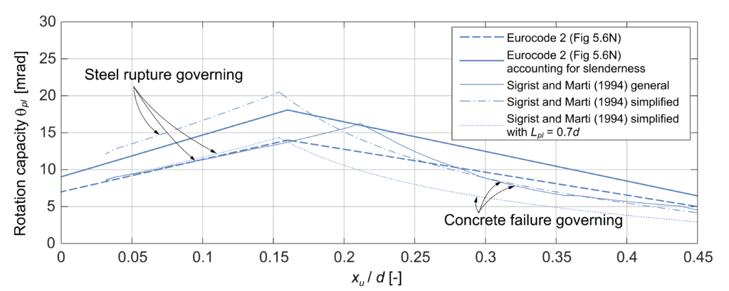
Figures 3 (a) to (d) show the influence of the concrete class, the steel ductility, the slenderness and the crack spacing, respectively.
The Eurocode provides a single relationship for the rotation capacity of concrete classes < C50/60. The models based on the Tension Chord Model predict a decrease of the rotation capacity for higher concrete strength if the reinforcement rupture is governing and no influence if concrete failure is governing. While this may seem counterintuitive initially, it can be explained by the relation of the bond stress and the concrete tensile strength according to the Tension Chord Model. Higher bond stress means a more considerable influence of tension stiffening and thus a lower mean steel strain over the crack element and a lower rotation capacity.
Using high ductile steel the models predict a higher rotation capacity, as expected, and concrete failure becomes governing at lower mechanical reinforcement ratios. The Eurocode allows multiplying the proposed bilinear relationship by a factor kλ, accounting for the slenderness of the structure. The general method by Sigrist and Marti (1994) shows a similar increase in rotation capacity with slenderness, but the simplified method does not consider slenderness.
The methods based on the Tension Chord Model reflect that a larger crack spacing has a negative impact on ductility. The bilinear curve proposed by the Eurocode does not consider crack spacing. This may also be an advantage considering the difficulty of crack spacing estimates due to its stochastic nature.
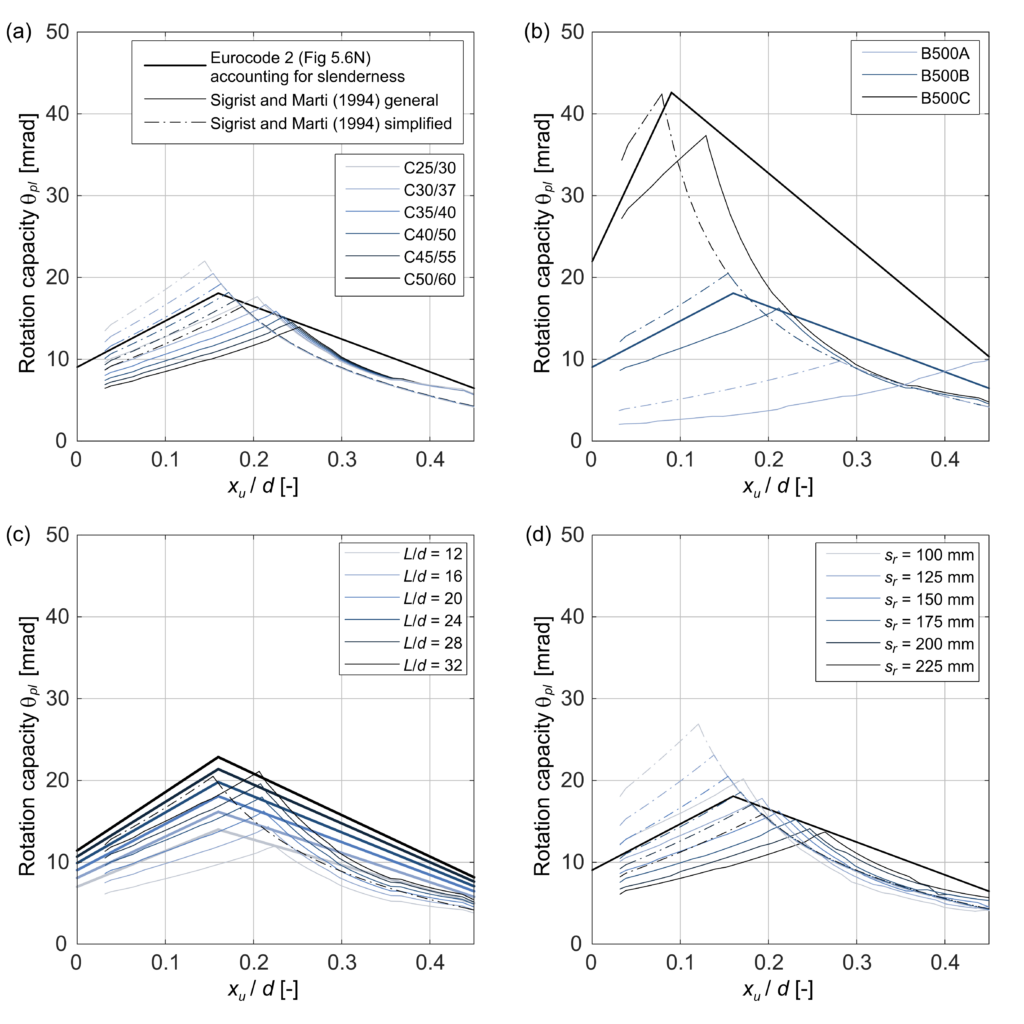
Let’s summarise the main conclusions from the comparison of the methods and the parameters studies
- The plastic hinge length has an important influence on the results of the simplified method proposed by Sigrist and Marti (1994), but it is hard to estimate in advance.
- The influence of slenderness is not included in the simplified method.
- The Eurocode gives tendentially higher estimates of the rotation capacity when concrete failure is governing because the proposed relationship is linear (compared to the nonlinear relationships of the other methods)
A specific structure design corresponds to a single point in these diagrams. As both the Eurocode and the simplified method by Sigrist and Marti (1994) are very simple to apply, it may make sense to compare both results in practice.
While the difference between the results of the different methods may seem significant, it is essential to note that the scatter between experimental results is also quite pronounced. This justifies the use of a simple approach (instead of a refined one) for checking the deformation capacity but calls the general validity of such checks into question.
A direct check of ductility (as a ratio of e.g. the rotation at failure and yielding) is not performend for static problems. While the calculation of the rotation ductility in plastic hinges is discussed in expert literature, hardly no informations is provided on the ductility requirement.
What’s the relation between the check of deformation capacity and ductility?
While structural engineers are generally familiar with the concept of ductility, it is often confused with other, related concepts such as deformation capacity and demand.
The definitions in the SIA 260 state that ductility is deformation capacity characterised by irreversible deformations and energy dissipation, wherein deformation capacity comprises the elastic and plastic deformations of a structure up to failure. Thus a ductile structural element is one that can support large inelastic deformations while dissipating energy, i.e. not softening before it fails. The concept of ductility is not directly related to the acting loads or the deformation demand.
In contrast, the check of deformation capacity compares the deformation capacity with the deformation demand in a design situation, according to Eurocode 2. Suppose the stress resultants in general or in a region are low. In that case, the check of deformation capacity can be fulfilled even if the deformation capacity in itself is not particularly high. This has positive and negative consequences. On the one hand, providing a high deformation capacity in regions that will most likely never reach yielding seems unnecessary. On the other hand, unforeseen loads or self-equilibrated stress states may lead to an unexpectedly large deformation demand, in which case a lack of deformation capacity may prove fatal.
One of the main difficulties in assessing the deformation demand is that self-equilibrated stress states influence it. Consider the example of an experiment on a two-span slab strip shown in Figure 4. Before starting the experiment, the initially plane specimen is subjected to a self-equilibrated stress state by moving the supports. This creates a hogging shape at a load of 0 kN, as seen in Figure 4. It is intuitively clear that the rotation demand at the intermediate support is higher in this case than if the specimen had not been subjected to an initial, self-equilibrated stress state. Consequently, unfavourable self-equilibrated stress states need to be considered to determine the rotation demand.
In the extreme case, one might require that the deformation capacity is larger than the deformation demand until the ultimate plastic load, associated with a plastic mechanism, is reached. That way, the deformation capacity is sufficient for any self-equilibrated stress state. Unfortunately, the SIA 262 does not provide information on how exactly to conduct a check of the deformation capacity and which actions to consider in the determination of the deformation demand.
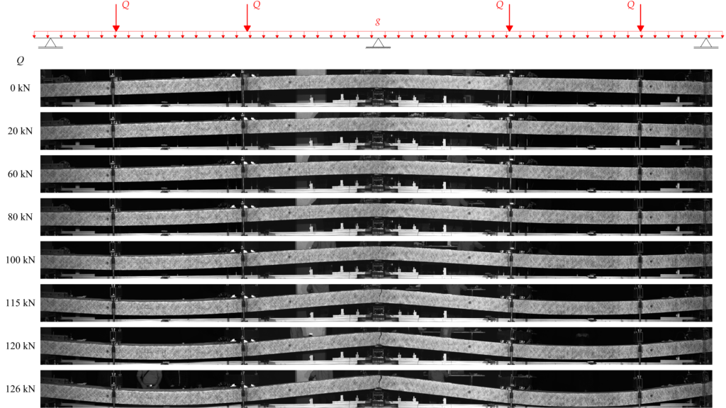
What’s the conclusion from all of this? Where do we want to go?
This blog post introduced the topic of ductility in the design of reinforced concrete structures subjected to static loads and presented two simple methods to estimate the rotation capacity to check the deformation capacity in practice. Then it explained the relation between the concept of ductility and the deformation capacity check.
One current issue is that the SIA 262 does not include methods to provide ductility in structures that do not comply with the usual construction rules. If, e.g. reinforcing material that does not comply with ductility classes B500B or B500C is used, the redistribution of stress resultants is only possible with a check of deformation capacity. This is a severe restriction for innovative materials and fabrication technologies, e.g. for new types of reinforcement or digital fabrication, because the presented methods for the estimation of the rotation capacity are limited to specific applications: they work well on one-way carrying structures but cannot be applied to two-way carrying slabs for example. Furthermore, the check of deformation capacity is challenging due to the dependence of the deformation demand on self-equilibrated stress states.
Current research aims at finding a strategy to design structures composed of materials with low ductility, softening or even brittle behaviour in certain regions, where they don’t endanger the overall ductility.
For this purpose, the ideas of Capacity Theory may be applied to elastic-plastic systems, thus designing the structure such that failure occurs in a region with a high deformation capacity. A similar approach is the background of code provisions to avoid brittle shear failures in favour of bending failures.
Simultaneously an experimental series on two-span slab strips is carried out in collaboration between the chair of Concrete Structures and Bridge Design at ETH Zurich and the Institute of Civil Engineering (IBI) at the Lucerne University of Applied Sciences and Arts. Figure 4 shows an experiment on a slab strip reinforced with steel that has a large ultimate strain but hardly any strain hardening over a major part of the inelastic range. This is one in a series of 21 planned experiments with metallic reinforcement types, different ductility and strength levels, and non-metallic reinforcements. The ongoing research should aid the use of innovative materials and fabrication technologies and generally improve the understanding and awareness of ductility, deformation capacity and deformation demand in structural concrete.
Nathalie Reckinger
Comment this blog post on LinkedIn or Instagram
Link zur deutschen Version: Verhalten von statisch unbestimmten Stahlbetontragwerken im Brandfall
Large deformations are often observed in experimental fire tests on statically determinate structures, which suggests a large deformation capacity. Deformations are triggered initially by the temperature gradient between the surface exposed and the surface unexposed to fire, and subsequently increased by the temperature-dependent degradation of material properties. However, in statically indeterminate structures, rotations and/or axial expansions are restrained, e.g. at intermediate supports of continuous slabs or beams or at fixed end supports. Due to these restraints, temperature differences within the cross-section cause indirect actions whose magnitude depends on the static system, the stiffness of its members and the cross-sectional resistance.
The main structural effects of fire are highlighted in Figure 1, which shows the consequences of a fire exposure at the bottom of a statically indeterminate two-span slab strip documented by Kordina and Wesche (1979). Figure 1a shows the elastic bending moment distribution along the slab axis (i) at ambient temperature (denominated Md,el), assuming a uniformly distributed load and a ratio of design load at ambient temperature to that under fire conditions of qd/qd,fi = 1.4, and (ii) under fire conditions (denominated Mfi) at different fire exposure times t = [0, 5, 10, 15, 30] min, taking into account the actual load introduction points during the test. Kordina and Wesche (1979) state that the slab strip was designed with an intended moment redistribution of 15% of the maximum elastic hogging moment at ambient temperature; the redistributed bending moment distribution is indicated with the dashed line (denominated Md,pl) in Figure 1a. Figure 1b shows the variations of the bending moment and the support force at the intermediate support during exposure time t, indicating that positive curvatures caused by the fire exposure at the bottom side of the slab lead to a drastic increase of the hogging moment and vertical reactions at the intermediate support already at short exposure time. Figure 1c shows the measured maximum deflection in the span and an estimation of the corresponding plastic rotation at the intermediate support (calculated based on the deflections in the span) during exposure time t. Obviously, as soon as the yield moment was reached after 15 min fire exposure, significant plastic rotations took place, amounting to almost 120 mrad after 90 min, which by far exceeded those acceptable at ambient temperature (cf. provisions in the EN 1992-1-1).
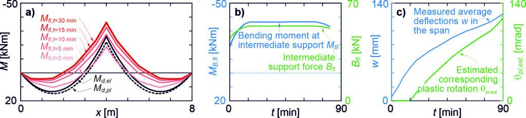
Within the framework of revising the EN 1992-1-2 on structural fire design, we reviewed several experimental campaigns on statically indeterminate members. We mainly focused the review on experimental campaigns led by Professor Karl Kordina and carried out at TU Braunschweig almost 50 years ago: Ehm et al. (1970) and Wesche (1974) reported several fire tests on continuous beams, while Kordina and Wesche reported nine fire tests on two-span slab strips. Figure 2 shows Beams 1 and 4 after their testing carried out by Wesche and Figure 3 shows Slabs 1,2, 4, 5 and 9 after their testing carried out by Kordina and Wesche.
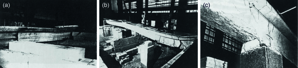
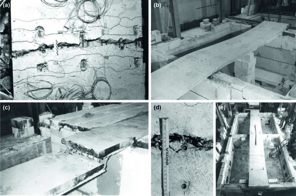
The findings from these experiments at TU Braunschweig had a direct impact on the design and detailing rules for statically indeterminate reinforced concrete beams and slabs given in the EN 1992-1-2:
- The hogging moment reinforcement needs to be extended into the span of continuous beams and slabs, as shown in Figure 4. In four experiments of Ehm et al. and four experiments of Kordina and Wesche, cracking at the end(s) of the top reinforcement in the region of the intermediate support occurred early in the experiment, even before the reinforcement yielded at the intermediate support (see Figure 3c). Such a failure may occur if the differences in the bending moment curves between ambient temperature and in fire conditions (compare also Figure 1a) are ignored when detailing the reinforcement.
- When considering this detailing rule of extended hogging moment reinforcement, static indeterminacy is generally advantageous for beams, allowing for reduced axis distances compared to static determinacy.
- The tabulated design data of EN 1992-1-2 for statically indeterminate members may be used up to a moment redistribution of 15% from the intermediate support to the span in ambient temperature design. EN 1992-1-2 indirectly limits overly low reinforcement ratios at the intermediate support by limiting the redistribution.
- A minimum reinforcement ratio of 0.5% is required over intermediate supports in continuous slabs where limited rotation capacity (cold worked reinforcement) or increased rotation demand (one-way continuous slab) is expected, and
- Two-way slabs and axially restrained slabs generally incorporate sufficient redundancy to avoid a bending failure under fire conditions, as Wesche (1985) and Wiese (1987) pointed out in their dissertations. For flat slabs, EN 1992-1-2 asks for (i) an increased thickness (e.g. hs = 200 mm for R90) than for slabs with line support and (ii), for R90 and higher, a minimum percentage of 20% of the top reinforcement in the column strip to be continuous over the entire span.
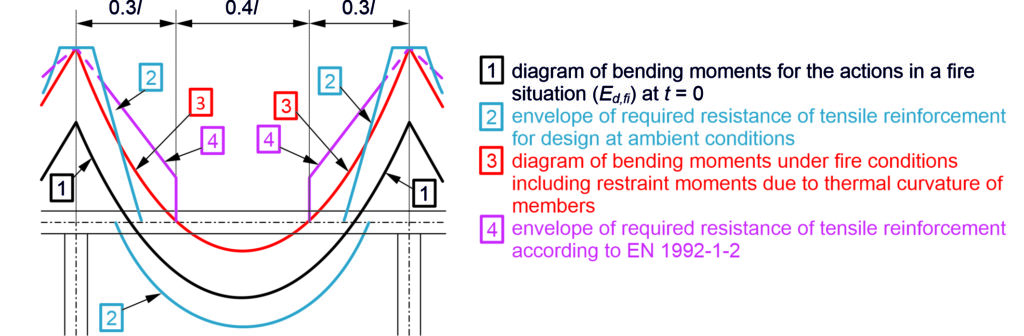
While respecting these design and detailing rules, continuous beams with reduced axis distances than for simply supported beams may be considered safe according to the current EN 1992-1-2 and sufficiently validated by experimental results. However, the design provisions for continuous slabs contain a considerable amount of extrapolation and engineering judgement, given the rather scarce evidence for one-way continuous slabs: only three of nine continuous slab strips of Kordina and Wesche survived longer than expected when using tabulated design data given in EN 1992-1-2. Accordingly, the rotation capacity of continuous slabs may not be taken for granted if no axial restraint can be mobilised (e.g. for typical two-span tunnel ceilings) nor two-way load carrying conditions prevail (many precast solutions).
Furthermore, plastic hinges caused by the high restraint moments under fire conditions are relevant for reliably modelling the global response of concrete structures under (partial) fire exposure. Therefore, we developed a model to assess the behaviour of members subjected to bending under fire conditions. The model builds on the Tension Chord Model, which was developed by Sigrist (1995) for studying the rotation capacity of members subjected to bending at ambient temperature. Our model is based on constitutive material properties given by EN 1992-1-2 and some complementary considerations concerning the biaxial compressive strength of concrete and strain hardening of reinforcement. The structural system is analysed using cross-sectional moment-curvature relationships established with the constitutive material properties and ensuring global equilibrium and compatibility.
Figure 5 compares (a) the bending moments MB at the intermediate support, (b) the maximum deflections wSpan in the span and (c) the reinforcement strains εsm,B averaged over 100 mm at the intermediate support in the slabs tested by Kordina and Wesche. Generally, the model predictions correlate well with the experimental results regarding the fire resistance, the evolution of the bending moments at the intermediate support, as well the deflections in the span. The comparison between test results and model predictions reveals a considerable effect of the concrete aggregate used mainly caused by the corresponding concrete thermal expansion.
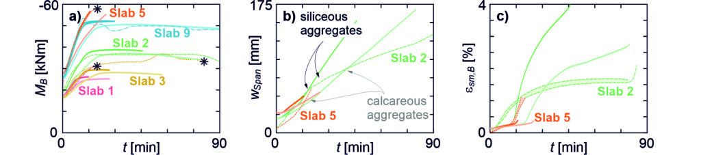
With the developed model, we conducted a parametric study aiming to (i) identify the most influential parameters for the structural fire behaviour of statically indeterminate systems and (ii) discuss whether design rules provided by EN 1992-1-2 can be safely applied to slabs and beams whose dimensions differ significantly from those featured in the tests used for validation. The parametric study explored the effect of uncertainties related to the modelling of statically indeterminate systems because not only the stiffness and strength, but also the internal actions are highly influenced by simplified material models. The following parameters are identified as the most influential ones:
- ductility of reinforcing steel (higher rotation capacity with higher ductility class),
- reinforcement ratio (higher rotation capacity with higher reinforcement ratio),
- concrete strength (higher rotation capacity with lower strength) and aggregate type of concrete (lower rotation demand with calcareous aggregates than with siliceous aggregates) and
- axial and rotational end restraint conditions (beneficial for fire resistance).
While engineers can specify the reinforcement ductility, reinforcement ratio and concrete strength in design, the concrete aggregate type generally cannot be specified and the restraint conditions are challenging to quantify. Accordingly, design recommendations given in EN 1992-1-2 and mainly developed at TU Braunschweig under the lead of Professor Kordina focus on the properties that can be influenced by the designer.
Based on our parametric study, the detailing rules given in EN 1992-1-2 are considered to remain valid for practical applications. The rotation capacity is sufficient for most studied slabs with a reinforcement ratio of 0.5% or higher. The detailing rules may not cover all eventualities such as the reduced rotation capacity when using high strength concrete, or large redistributions of shear forces towards the intermediate support. However, they are overall reasonably safe and easily applicable to cover most continuous slabs of current practice.
We also showed in our parametric study that results for modelled statically indeterminate systems are subject to considerable uncertainties if (i) information on the used material is incomplete or (ii) the used models do not or insufficiently cover all necessary information (e.g. lack of providing a hardening branch in the stress-strain relationship for reinforcing steel). Indeed, the concrete aggregate type with its corresponding thermal expansion or the consideration of strain hardening properties and tension stiffening may affect the fire rating across several standard fire resistances when modelling the behaviour of statically indeterminate bending members exposed to fire.
Patrick Bischof
Comment this post on LinkedIn or Instagram
Link zur deutschen Version: Einsatz Erweiterter Relität (XR) in der Lehre im Stahlbetonwicklung
Advanced analytical thinking and the ability to abstract are indispensable for understanding the content of lectures in structural engineering: real (3D) structures under different loading situations are investigated with support of computational surrogate models for structural analyses as well as the detailing of the reinforcement. Especially for civil engineering students with little professional experience, this abstraction in lectures is a hurdle. In structural concrete, this is aggravated by the fact that the models used abstract reality to a much greater extent than in other construction methods. Students usually only gain a deeper understanding of the subject matter in the course of reflection after the lecture or in subsequent exercises and colloquia. To meet these challenges, we are developing digital demonstrators and tools at our chair to support and improve teaching [1]. The main ideas behind this initiative are: (i) to complement typically paper-based instruction with digital content displayed via smart devices; (ii) to use mobile technologies available to students to support interactive, personalised, and self-motivated learning instead of content- or teacher-centered instruction; (iii) increase student engagement and enthusiasm for the lecture through immersion in the lecture content to promote deeper understanding at the individual level; (iv) modernise and digitise traditional teaching methods in civil engineering. To this end, the authors designed and implemented a mobile augmented or mixed reality tool (Struct-MRT) [4] and evaluated it in field studies among students and teachers.
Methods of extended reality and their use in teaching civil engineering
Extended reality (XR) is an umbrella term for all technologies that combine real and virtual environments as well as human-machine interactions generated by computer technology and mobile devices [2,3]. XR technologies create immersive digital environments within the so-called reality-virtuality continuum [2,2] to varying degrees depending on the intent, cf. Figure 1. Augmented reality (AR) is located on the left side of the reality-virtuality continuum in Figure 1, where the real world is augmented with digital content. “Google Glass” or “Bosch Smartglasses Light Drive BML500P” are typical AR devices here. Virtual reality (VR) is on the right side of the continuum, where the user is immersed in a completely digital environment via Facebook’s “Oculus Quest” device, for example, and hides the real world. Mixed reality (MR) lies between the aforementioned extremes and includes all technologies in which computer-generated content is mixed in varying proportions with the individual’s view of the real world. Currently, the most popular device for MR is the “Microsoft HoloLens” headset.

Currently, there is limited research on the development and integration of XR technologies into civil engineering teaching. However, there is scientific evidence that XR facilitates the learning of abstract and difficult-to-understand topics [4 – 6]. In addition, the global pandemic (COVID-19) that still persists has caused many universities and companies to change the way they work, teach, and learn. In our prototypical studies, content from various reinforced concrete lectures was developed as AR applications for smartphones and tablets, cf. Figure 2, and made available to other teachers as methodological workflows (Struct-MRT), cf. Figure 3.
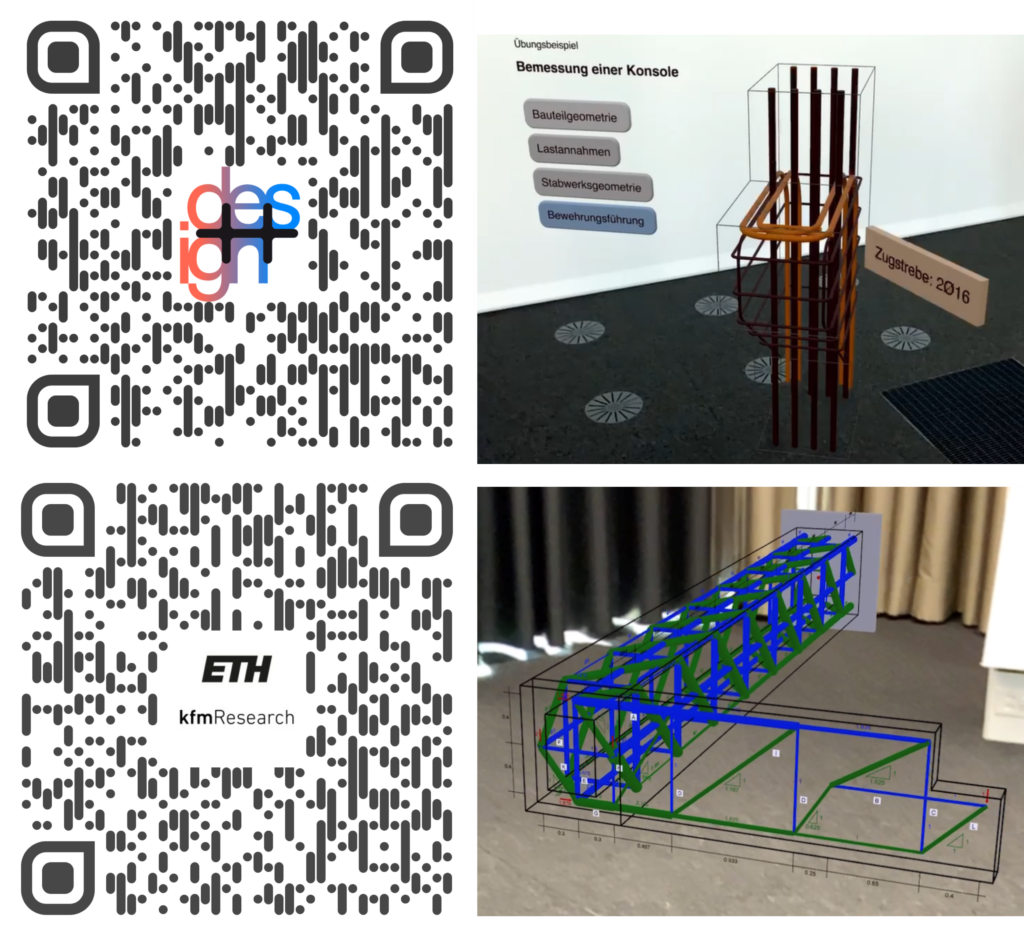
Modern XR-enabled smartphones and tablets are affordable and widely available among teachers and students, making this type of immersive teaching highly scalable at low cost. In two field studies, Struct-MRT was tested and evaluated with respect to the two examplary applications of a reinforced concrete bracket and a torsion beam in use in real teaching situations, see Figure 2 and [1]. Struct-MRT allows users to navigate interactively through the individual steps of structural analysis, design and reinforcement detailing. In addition to the true-to-scale, three-dimensional representation of the components, supplementary texts and formulas are dynamically displayed to explain the verification process. Thereby, we are transforming traditional paper-based instruction into immersive teaching, where mobile devices provide access to contextual visual information of the subject matter. Complex lecture content and exercises on structural modeling or construction details can be playfully illustrated and experienced in this way, along with structural design that conforms to standards. Finally, Struct-MRT enables a student-centered approach that allows individualised and self-motivated learning.
Struct-MRI workflow of an exercise and application example
User interactions with Struct-MRT applications are shown as a sequence diagram in Figure 3 (left). During a lecture, students can access the additional content of an assignment sheet by scanning a QR code with their mobile device (iPhone/iPad) via the built-in cameras. When they then open the app on their device, computer-generated 3D content including multimedia (e.g., images or formulas) is displayed (see Figures 2 and 3). The views of the developed apps are designed in full-screen mode and support both portrait and landscape orientation. Additional graphical interaction widgets are placed along the 3D content depending on the specifics of the deployment example.
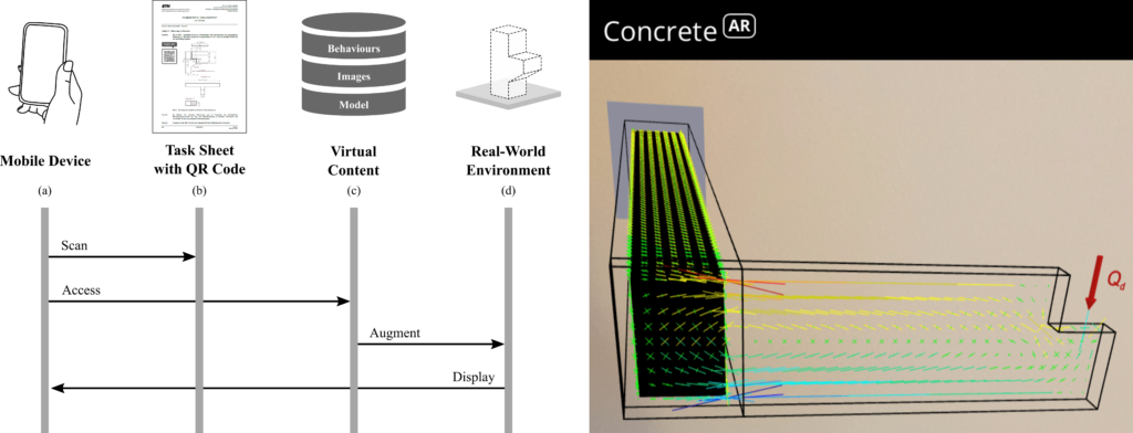
In the past fall semester, an exercise on the design and construction of a torsion beam was enriched with AR apps. In addition to the paper-based documents, the students were able to use six AR apps (cf. Figure 3 (center)) in parallel to obtain spatial impressions regarding the geometry of the beam, modeling with trusses or stress and deformation results of the finite element method and to interact with them in an immersive way. After the exercise, the approximately 40 participants of this field study (panel) were surveyed using a comprehensive questionnaire regarding the following objectives:
- Judging the usability, impression, and interactivity.
- Determining the potential and acceptance of the use of XR in engineering education and knowledge transfer among the study participants.
- Identifying possible deficits and potentials for improvement of MR apps.
- Identifying further suitable use cases of the MR apps.
The following hypotheses were tested as part of the survey:
- H1: The benefits of mixed reality are easy for students to grasp.
- H2: The use of mixed reality technologies and tools is easy for students to learn.
- H3: Students recognise the benefits of mixed reality technologies for teaching and learning.
- H4: Students enjoy working with mixed reality technologies and tools.
Statistical tests show that all four hypotheses can be considered true. These results support the authors’ core assumption for the use of XR in teaching: the presentation of contextual 3D models to illustrate content is a promising approach in teaching.
The study provided further insights into the use cases of XR in civil engineering. The panel clearly saw the greatest benefits of XR applications in structural engineering, followed by construction or infrastructure management. The results suggest that the perception and understanding of particularly complex structural systems with elaborate design and dimensioning tasks can be strongly supported by XR. The panel also provided indications of additional supporting functionality that can be added to future versions of Struct-MRT workflows and applications. Further findings and statistical analyses of this study can be found in [4].
Conclusion and Outlook
In summary, the results of our pilot studies show that augmented reality methods have not yet sufficiently arrived in everyday study and teaching, but the picture of a broad acceptance of this technology among civil engineering students at ETH Zurich is emerging. The developed applications provide better support for the learning process through the interactive workspace and promote student interaction with course content through immersion in multimedia-based learning environments. In addition to the potentially transformative added value of augmented reality in structural concrete teaching, the surveys simultaneously provided insight into the technological, organizational, and cognitive challenges of its use in teaching and learning. The development and implementation of augmented reality applications complements our range of digital learning applications and in particular offers opportunities for immersive learning experiences during lectures and exercises. We would like to invite you to explore our applications yourself via [1].
Acknowledgements
A big thank you goes to all participants who contributed to the implementation of the applications and of course to all participants of the accompanying field studies.
Project Lead: Prof. Dr. Walter Kaufmann, Dr. Michael A. Kraus
Applications Programming: Irfan Čustović
Supervision Tutorials: Simon Karrer
Links
Collection of all Concrete Teaching Applications: https://concrete.ethz.ch/applikationen/
Literature
[1] https://concrete.ethz.ch/blog/lernen-zu-lernen-digitale-lernapplikationen-in-der-stahlbeton-vorlesung/
[2] Milgram, P., & Colquhoun, H. (1999). A Taxonomy of Real and Virtual World Display Integration. Mixed Reality, 5–30.
[3] Osorto Carrasco, M. D., & Chen, P. H. (2021). Application of mixed reality for improving architectural design comprehension effectiveness. Automation in Construction, 126(March).
[4] Kraus, M., Custovic, I., & Kaufmann, W. (2021). Struct-MRT: Immersive Learning and Teaching of Design and Verification in Structural Civil Engineering using Mixed Reality. arXiv preprint arXiv:2109.09489.
[5] Sampaio, A. Z., & Martins, O. P. (2014). The application of virtual reality technology in the construction of bridge: The cantilever and incremental launching methods. Automation in Construction, 37, 58–67. https://doi.org/10.1016/j.autcon.2013.10.015
[6] Shirazi, A., & Behzadan, A. H. (2015a). Content delivery using augmented reality to enhance students’ performance in a building design and assembly project. Advances in Engineering Education, 4(3), 1–24.
Michael Anton Kraus
Comment this post on LinkedIn or Instagram
Link zur deutschen Version: Entwicklung eines Brückensystems aus CFK-vorgespanntem UHB für die SBB
When looking for a system solution for railway bridges with short spans, e.g. flyovers, the standardised “Walzträger in Beton” (WIB) bridges are often used. This bridge type is frequently encountered in the Swiss railway network and impresses with its simple design, well-known load-bearing behaviour and slenderness. However, disadvantages are high material consumption (full concrete slabs with steel girders) and reduced durability (exposed lower flanges of the steel profiles). For these reasons, SBB (Swiss Federal Railways) looks for an alternative bridge system to overcome the mentioned shortcomings. A preliminary inventory analysis by SBB shows the need for such a system with minimal maintenance and route closures: It estimates that on the SBB network, around 800 existing track bridges with spans between 2 and 10m are assessed with condition classes 3 (“sufficient”) or 4 (“poor”). This means that measures will be necessary on these structures in the foreseeable future. Although not all these condition-critical bridges need to be replaced, and many new constructions will be designed as closed frames, SBB sees a great need for single-span bridges in the span range of 2 to 10m.
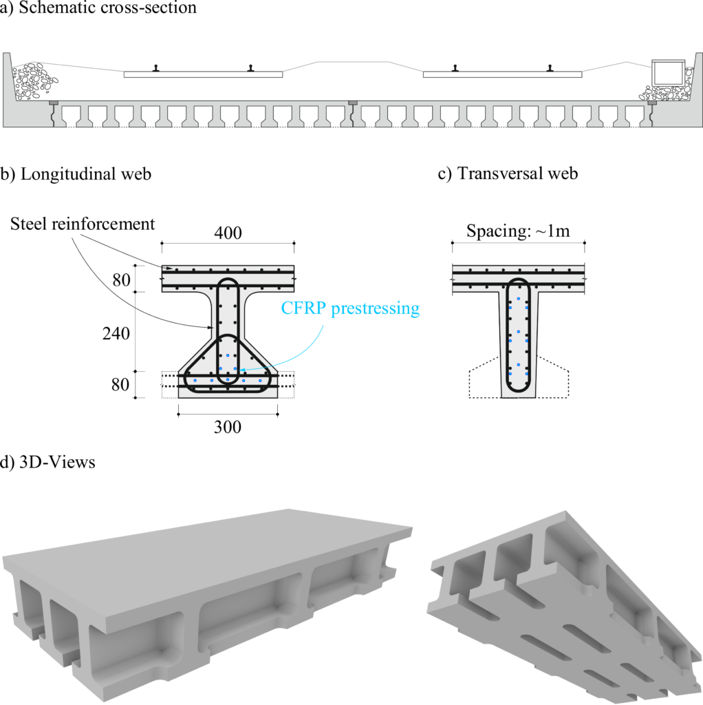
At the Chair of Concrete Structures and Bridge Design, research is conducted under the direction of Prof. Dr. Walter Kaufmann and Dr. Karel Thoma with the goal to develop a system solution that overcomes the disadvantages of WIB bridges. Design and materialisation are entirely focused on durability and fast erection (high degree of prefabrication). The basic concept is shown in Figure 1. The ultra-high performance concrete (UHPC) allows a slender construction due to its high strength, and its impermeability prevents entering of corrosion-inducing substances. Under serviceability loads, the system should remain uncracked, which reduces deformations due to the high uncracked stiffness and prevents the formation of corrosion-promoting cracks. Consequently, the bridge system is prestressed longitudinally and transversely. Pre-tensioned carbon fibre reinforced plastic (CFRP) is used for durability and monitoring reasons instead of conventional steel for the prestressing. The CFRP bars are pre-tensioned in a tensioning frame and positioned in the formwork together with the steel reinforcement. After casting and concrete hardening, the CFRP bars are released from the tensioning frame, whereby they anchor themselves in the concrete through friction and induce a normal compressive force to the concrete. Figure 2 shows schematically the pre-tensioning process, which takes place in a prefabrication factory.
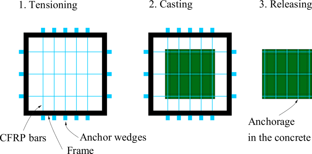
In addition to the CFRP prestressing, conventional steel reinforcement is used, as already mentioned, which provides a more ductile load-bearing behaviour. A system with only CFRP would behave approximately linearly elastic until failure. The chosen variant with a lower flange and inspection openings (Figure 1 d) allows for a slender design and an arrangement of the longitudinal prestressing bars in the flange, reducing the necessary amount of CFRP bars and separating the longitudinal prestressing from the transversal. Disadvantages – e.g. compared to an open cross-section without lower flanges – arise in the visual inspection capability during operation and in the formwork technology.
This project aims at developing a reliable system solution that will ultimately be approved by the Federal Office of Transport. To achieve this, as a first step, scientific questions related to the load-bearing behaviour of the concrete-steel-CFRP composite material, which to the knowledge of the project team has never been used for a railway bridge in Switzerland before, have to be answered. A schematic overview of the scientific questions is given in Figure 3. Particular attention is paid to the cyclic behaviour of the composite material: How does the material behave after 1, 2 or 4 million load cycles? In particular: How does the ratio of bond stresses between reinforcement and prestressing (Factor ξ according to SIA 262, 4.3.8.1.5) evolve with the load cycles? To address these questions, an extensive series of experiments together with our partners at HSLU and Empa is planned. At ETH, we focus on the tensile behaviour (see Figure 3 a) and the simulation of the bridge slab (Figure 3 e). From the tensile tests, we will extend the tension chord model (TCM) [1] to CFRP prestressing, which will allow us to model the load-deformation behaviour and the ductility of the material, including the effects of cyclic loading. The adapted TCM will serve as a basis for a universal material model, which will be implemented into a nonlinear FE framework analogously to [2] in order to perform a large-scale numerical parameter study to determine the final design of the bridge system. Prof. Dr. Giovanni Terrasi and his team at Empa work intensively on the pre-tensioning and the development of a clamping anchorage system for the CFRP prestressing. Furthermore, they will be dealing with the bond behaviour of CFRP in the anchorage region (Figure 3 c) and the cyclic behaviour of a statically determined beam in bending and shear (Figure 3 b). HSLU, under the direction of Prof. Dr. Albin Kenel, is – in addition to all questions regarding concrete technology, the systematic measurement of material properties and questions regarding curing (UHPC is very susceptible to shrinkage due to its high cement content) – concerned with the pre-tensioning frame, the redistribution of loads in the bridge in case of eccentric loading (Figure 3 d) and fire behaviour.
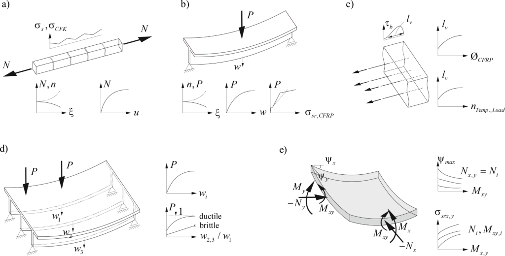
The first highlight of the project is a large-scale test on a 2 x 6m section of a bridge. The test serves as a “proof of concept” to show that (i) we can manage the construction and (ii) the mechanical behaviour permits use for the SBB. The challenge of producing this first large bridge section is taken up by alphabeton AG who is responsible for the production of all specimens in the project. The biggest challenges are the formwork and the prestressing, which requires careful planning, particularly regarding occupational safety.
The large-scale test will be carried out in spring/summer of 2022 in the construction hall at ETH Hönggerberg. We will keep you posted about the further course of the project, which will include the design of the system solution and a dimensioning tool with a subsequent pilot project on the SBB rail network, here in our blog.
References
[1] Alvarez M. Einfluss des Verbundverhaltens auf das Verformungsvermögen von Stahlbeton. Tech Rep 236, Institut für Baustatik und Konstruktion, ETH Zürich;1998. http://dx.doi.org/10.3929/ethz-a-002000033.
[2] Thoma K, Roos P, Weber M. Finite-Elemente-Analyse von Stahlbetonbauteilen im ebenen Spannungszustand. Beton- Stahlbeton 2014;109(4):275–83. http://dx.doi.org/10.1002/best.201300087.
Andreas Näsbom
Comment this post on LinkedIn or Instagram
Link zur deutschen Version: Über das Aufkommen von digitaler Fertigung mit Beton
Digital fabrication with concrete (DFC) has emerged as a new trend in the construction industry over recent years. But where does this trend come from, and what is DFC? In this blog contribution, we want to introduce you to the topic of DFC and address the most pressing questions in this field.
What is Digital Fabrication with Concrete?
Digital Fabrication with Concrete describes various fabrication methods where concrete elements are produced in an automated process. With these technologies, almost any type of concrete element can be produced without or with limited formwork and optimised for material usage (Wangler et al. 2019). Therefore, these new processes claim to make the construction industry more efficient and reduce its negative environmental impact. From the various processes that exist, 3D concrete printing (3DCP) is the most widely applied. In 3DCP, a concrete element is produced by adding layers on top of each other, just like in conventional plastic 3D printers.
What’s the history behind these new technologies?
The first automated and layered production of a concrete structure dates back to the 1940s. The Urschel Wall Building Machine was used to build a circular concrete structure with an automated system.
After the first emergence, not much development could be observed in the following decades. In the early 2000s, Prof. Khoshnevis (Khoshnevis 2004) published his work on contour crafting and set off a surge in research and development in 3DCP and other DFC technologies. Today, companies and institutions are using and researching these new technologies all around the world. The most prominent applications are the construction of entire buildings, such as a residential house recently constructed in Germany. Various DFC technologies were used to fabricate the DFAB Housing unit at the NEST building at EMPA. The application of DFC is, however, not only limited to houses. A wide range of applications can be found in various areas such as artistic installations, bridges, infrastructure elements, etc. (see figure below).

What are the current challenges?
The advancement of DFC technologies, especially 3DCP, faces various challenges. Researchers and builders worldwide are rushing to address these challenges. The main research areas cover material, architectural and structural considerations. On the material level, the fresh and hardened properties, the material composition, and the processing are some of the main areas of interest. For architects, new opportunities and limitations for design arise. The entire building catalogue, including the building systems, can be rethought if DFC is used.
One of the main challenges (and the focus of the author’s research) is the structural application of DFC. Due to the lack of reinforcement approaches, to date, most projects use printed concrete as masonry or as a lost formwork (i.e. to cast a conventional reinforced concrete element inside the printed shell). However, it is questionable if 3D printed concrete (typically with high clinker content) used as masonry or lost formwork leads to more sustainable construction.
Therefore, the range of DFC elements should be expanded into load-bearing applications similar or equal to conventional reinforced concrete to have a lasting positive impact on the construction industry. Therefore, new reinforcement strategies are needed. However, the addition of reinforcement to DFC and especially 3DCP is not straightforward. Without reinforcement, DFC structures designed according to today’s standards can only be used if only compressive stresses occur, no load-bearing requirements exist, or tests verify the structural performance. Accordingly, there is no framework suitable for the mass market telling us how to reliably design and build DFC structures. All these challenges need to be addressed while at the same time keeping general considerations such as socio-economic impacts and sustainability in mind. More details on the current challenges for digital fabrication with concrete are addressed in various review papers such as (Wangler et al. 2019), (Khan et al. 2020) and (Menna et al. 2020).
What is going on at ETH Zurich?
In the year 2014, the NCCR Digital Fabrication funded by the SNSF was initiated. It is a swiss wide “initiative to lead the development and integration of digital technologies within the fields of architecture and construction” (dfab.ch). The project is divided into different research areas addressing different aspects of the digitalisation of the construction industry. One of the research areas focuses on DFC. Within this area, various technologies such as Smart Dynamic Casting (Lloret Fritischi 2016), Eggshell (Burger et al. 2020), Mesh Mould (Hack 2018), KnitCrete (Popescu 2019) and 3DCP (Anton et al. 2020) are being studied in an interdisciplinary manner (see figure below).
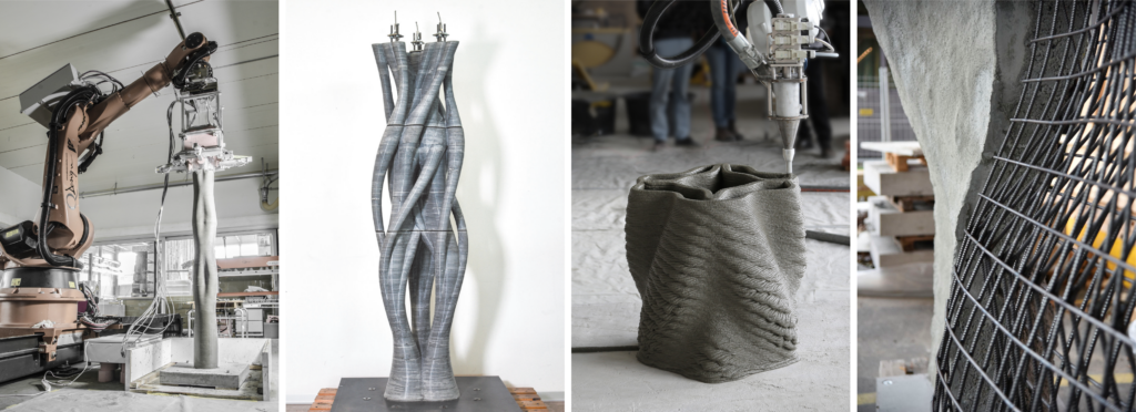
The Chair of Concrete Structures and Bridge Design focuses on the structural aspects of these new technologies. We ask ourselves, how can we build structurally sound elements? How can we create a win-win situation in the combination of reinforcement with DFC processes? Are there reinforcement approaches that could not establish themselves in conventional reinforced concrete but could have new opportunities in the field of DFC? How will we connect the elements, and how are the loads transferred?
With a team of doctoral students and PostDocs, we address these questions by producing structural elements, testing them in our laboratories and, if necessary, adjusting existing models or developing new ones. The figure below shows some examples from our current studies.
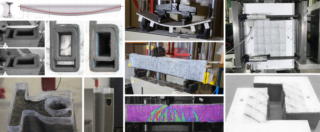
What’s next?
The dreams for DFC technologies are big. From printing multistory buildings up to colonies on Mars. However, DFC technologies are still in a nascent stage. Many limitations still need to be overcome before DFC becomes a main part of the construction industry. The construction industry faces some major challenges in the coming decades. DFC is an exciting area of research that will play a role in providing solutions, but how large of a role remains to be seen.
Lukas Gebhard
Comment this post on LinkedIn or Instagram
Link zur deutschten Version: Performanzbasierter generativer Entwurf von Netzwerkbogenbrücken
The method of Generative Design (GD) [1] has recently been introduced to the AEC community and marks a shift in conceptualizing, designing, and construction of the built environment. The basic idea behind GD is the efficient generation of design alternatives of a parametric model of an asset, together with defined design goals (performance criteria) and constraints in order to enable stakeholders to conduct information- and data-based decision-making. To that end, GD is a design automation and optimization method, which so far has already found its way into engineering practice software, such as AUTODESK REVIT [1], and published case studies [2].
In civil engineering, the design of infrastructure assets and especially bridges would be potential candidate applications for Generative Design. On the other hand, today, no mature fully digital and thus computational design nor optimization approach for bridges is available due to the complexity of the task caused by non-linear interactions of bridge components and a tremendous amount of geometric and material design variables. Hence, bridge optimization is cumbersome, time consuming and heavily dependent on the prior experience of the individual engineer. Evaluation of design insights and patterns are shared in limited ways but inaccessible to systematic and methodical assessment by modern Machine Learning (ML) algorithms, cf. Figure 1 (left).
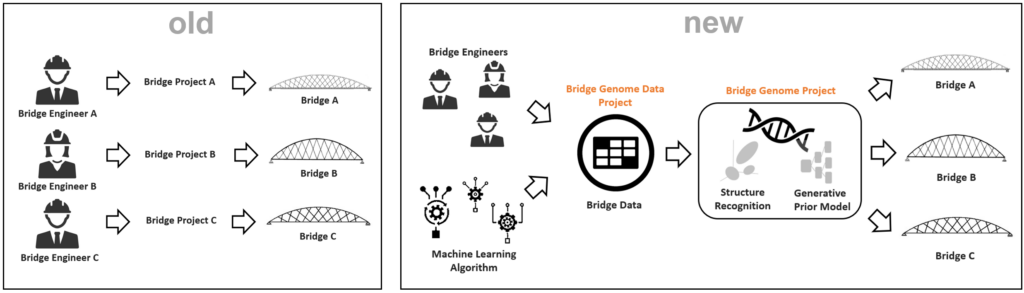
In order to tackle the mentioned problem of current bridge design, we initiated the “Bridge Genome Project”, which evaluates the research hypotheses that conceptual design, as we know it today, can be greatly assisted and improved by the use of modern ML methods together with databases of existing structures and GD. The concept of how this can be achieved is shown in Figure 1 (right). The idea behind the “Bridge Genome Project” is to mine information of existing structures to identify underlying patterns of bridge design (the “design genome”), which is then used as a starting point for further GD studies for new project situations. In order to establish a proof of concept, this research was concerned with network tied-arch bridges.
The proposed workflow consists of five necessary steps, cf. Figure 2:
- collection of structural data on bridges into a database;
- performing cluster analysis by unsupervised ML algorithms;
- performing predictions by regression/classification ML algorithms to generate prior bridge models;
- feed prior bridge models into a GD process via a parametric design software such as Grasshopper / Rhino [4];
- optimize design alternatives with parametric design software.
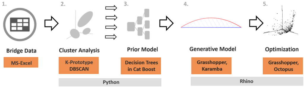
Based on a pre-processed data set of existing network tied-arch bridges all over the world, a cluster analysis was performed to find latent structures within the bridge data via two unsupervised learning algorithms K-Prototype [5] and DBSCAN [6]. A consistent structure was identified by both algorithms showing strong similarities of all bridge parameters for network tied-arch bridges that are within similar span ranges, cf. title Figure. Subsequently, a prior model is trained on the clusters, which is capable of predicting suitable bridge parameters for a new project situation in a predefined order. As this involves handling of mixed data types, the CatBoost [7] algorithm is employed here to provide regression and classification capabilities.
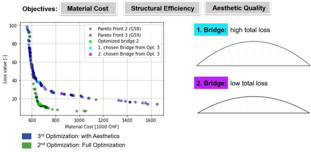
After generation of designs with this prior model through sampling suitable design parameters, the optimization of the parametric structural models is orchestrated using Grasshopper and Karamba3D in the Rhino 7 environment. To that end, the generative model can provide real-time structural analysis feedback for any parameter changes. Furthermore, the plug-in Octopus is applied to conduct multi-objective optimizations of the bridge parameters using the genetic optimization algorithm HypE. This study investigated objective functions concerning material costs, structural efficiency (for sake of simplicity 2D with linear elastic material behaviour), as well as a novel ML-based predictor for aesthetic quality. An example optimization result is given in Figure (3), involving (i) material costs and structural efficiency (Pareto-front marked by green dots); (ii) material costs, structural efficiency and aesthetics perception (Pareto-front marked by purple dots).
With this proof of concept study on network tied-arch-bridges, the developed multi-step ML approach for an automated GD of bridges is found to be a valuable assistance to the structural engineer, especially in the early design phases of a project. Our approach allows for an efficient structural design and optimization process of bridges and provides a template framework, which can be directly applied to other suitable data sets of other frequently used types of structures in the built environment, such as hangars or houses. The proposed ML approach allows to identify, extract and analyze design patterns contained in the built environment through the clustering step, which triggers further engineering insight but also discussions. The calibrated prior model formalizes this design knowledge and allows for sampling new designs at an early project stage. The so generated designs can then be fed to the Grasshopper/Rhino optimization loop to gain performance information (e.g. structural utilizations, deformations, but also aesthetics and sustainability aspects) in an automated manner. On the other hand, we identified a few limitations in this approach, which are the epistemic uncertainty of the prior model based on the small size and censoring of the data set for model training. In addition, the input of expertise and creativity by a structural engineer remains necessary as the machine-learning model might have learned potential unfavourable designs from the data, innovations are rare in this formulation of the GD approach, and Pareto-optimality enforces final stakeholder decision on the balancing of several performance objectives (e.g. economy vs utilization).
Michael A. Kraus
Comment this post on LinkedIn or Instagram
Literature
[1] https://www.autodesk.com/solutions/generative-design
[2] https://archistar.ai/blog/4-examples-of-generative-design-in-action/
[3] Kuhn, S. (2021): Parametric Modelling and Generative Design – A Multi-Step Machine Learning Approach for Design and Optimization of Network Tied-Arch Bridges, Master Thesis, ETH Zurich
[4] McNeel, R., & others. (2010). Rhinoceros 3D, Version 7.0. Robert McNeel & Associates, Seattle, WA.
[6] https://scikit-learn.org/stable/modules/generated/sklearn.cluster.DBSCAN.html
[7] Dorogush, A., Gulin, A., Gusev, G., Kazeev, N., Prokhorenkova, L., Vorobev, A. (2017): Fighting biases with dynamic boosting, arXiv:1706.09516.
Link zur deutschen Version: Zum Brandingenieurwesen im Stahlbetonbau
A room can be heated by fire to over 1000°C in a few minutes, depending on its size, ventilation conditions and the actual fire load. Increased temperatures induced by fire action cause for reinforced concrete structures:
- heating of the cross-section depending on its thermal material properties,
- degradation of the mechanical material properties (strength and stiffness) depending on the corresponding temperatures in the cross-section,
- an increased propensity to explosive spalling in some cases, and
- altered internal actions and reactions for statically indeterminate structural systems.
Various parameters influence the behaviour of reinforced concrete structures under fire exposure, mainly the fire load, the composition of the concrete and its moisture content, stresses and strains of static or thermal origin, the cross-sectional geometry, as well as the structural detailing. For example, columns are subject to increased deflections or statically indeterminate bending members experience increased shear or support forces depending on the fire exposure, the used material, and the structure. Increased column head deflections were the main reason for the failure of a warehouse in Ghent (1974) (see image), while force redistributions to intermediate columns were partly responsible for the failure of an underground car park in Gretzenbach (2004) (see image).
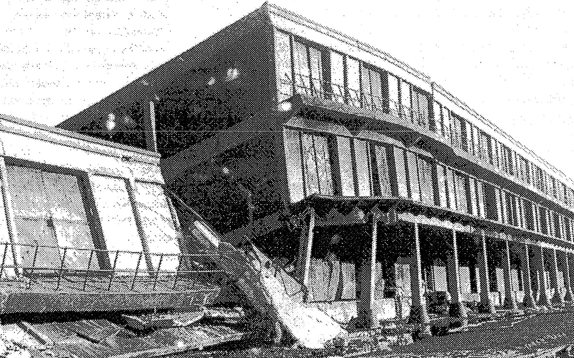
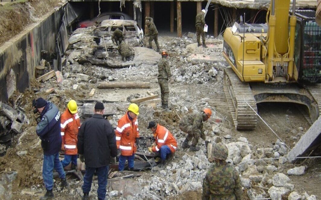
It is often difficult or impossible to explain all phenomena occurring in practical cases of damage caused by fire and in large-scale (representative) fire tests. After extinguishing a fire in buildings, it is only possible to determine which damage occurred at what instant with great uncertainty. In fire tests, only the temperature, deformations, and external forces can reliably be measured to discuss the tested member’s local and global behaviour. Nevertheless, thanks to extensive experimental studies (supplemented by theoretical considerations) on the fire behaviour of reinforced concrete structures between 1960 and 1990 (e.g. at the Technical University of Braunschweig under the direction of Prof. Kordina), it was possible to derive simple tabulated design data, detailing rules, and easily applicable material models to verify the fire resistance under standard fire conditions. Thereby, fulfilling fire safety requirements for reinforced concrete structures is, in most cases, a straightforward engineering task – justifiably because reinforced concrete structures exhibit a favourable behaviour in case of fire with the cross-sectional dimensions and concrete covers currently adopted. The favourable behaviour of reinforced concrete in case of fire is mainly because (i) concrete heats up comparatively slowly and consequently protects the reinforcement from being heated, (ii) reinforced concrete cross-sections are massive compared to cross-sections made of other building materials and (iii) concrete does not burn and, consequently, does not contribute to the fire load. Accordingly, the fire resistance of concrete structures is guaranteed in most cases by conceptual decisions and quick verifications using tabulated design data.
An excellent example of this favourable behaviour is the fire of the seven-storey car park of the Liverpool Echo Arena (dimensions: 70 m x 60 m) in 2017. The fire and fire load in Liverpool was unprecedented in its extent (up to 1400 vehicles burnt out during several hours) because the initial fire in one car quickly spread to other vehicles. The car park consisted of columns, beams, staircase cores, and prefabricated ribbed floor elements. Some of the ribbed floor elements were severely damaged or collapsed completely, but the rest of the structure remained practically undamaged (see image, reference: Structural-Safety).

However, simple tabulated design data may be insufficient or inapplicable for designing or assessing structures with a high risk of damage or personal injury (e.g. hospitals, high rise buildings, tunnels) and members with high slenderness or of new concrete types. In such cases, an in-depth understanding of the fire behaviour of reinforced concrete buildings is necessary to conscientiously carry out the design or assessment without tabulated design data. Keeping the efforts to achieve carbon neutrality in mind, studies going beyond the application of tables may be increasingly necessary because:
- the use of alternative engines such as lithium-ion battery engines generate fire curves whose consequences on reinforced concrete structures have not yet been widely studied (NB: today’s tabulated design data of EN 1992-1-2 and SIA 262 only apply for the standard fire curve),
- new ways will be (must be) found to efficiently produce members and structures with less massive reinforced concrete cross-sections than today – such as with filigree ribbed structures –, and
- newly developed types of concrete (such as recycled aggregate concrete, dense concretes, (ultra)high-strength concretes, etc.) with higher propensity to explosive spalling will be (must be) used increasingly.
Explosive spalling of mainly precast concrete under fire conditions has brought fire safety engineering to the table of the civil engineer in Switzerland over the last ten years – and also to my table when starting my scientific work in Prof Walter Kaufmann’s group at ETH Zurich. After initial work on this issue with the idea of expanding the basis for the Corrigenda C1 of SIA 262 in 2017, we could expand our knowledge on fire safety engineering continuously over the last four years while working in the project team to revise the current EN 1992-1-2.
Keeping the relevance of fire safety engineering in mind, fire safety engineering is integrated into the course “Advanced Structural Concrete” (Master’s programme in Civil Engineering at ETH Zurich) and, since 2021, also into the MAS studies on Fire Safety Engineering (established and organised by the Chair of Timber Structures from ETH Zurich). We introduce the material and structural behaviour under fire conditions and present the application, strengths, and limitations of the verification methods available in the standards. Based on this knowledge, we foster the ability to check the plausibility of the results obtained by advanced design methods. Furthermore, we give an overview for the evaluation of the fire safety assessment of existing structures. Last but not least, we want to convey an understanding of the assumptions underlying the standard to make future designers recognise the engineering challenges not covered by them.
Patrick Bischof
Comment this post on LinkedIn or Instagram
Link zur deutschen Version: Riccardo Morandi – Pionier im Brückenbau oder schlechter Ingenieur?
Morandi’s Polcevera Viaduct
The Polcevera Viaduct, over a kilometre long and built between 1963 and 1967, carried the A10 motorway at a height of approximately 40 m over the Polcevera River, the Turin-Genoa railway line, two marshalling yards and an industrial area. Soon after its inauguration (see picture gallery) the three prominent 90 m high pylons supporting the approximately 220 m long main spans made the viaduct a landmark of Genoa and one of Riccardo Morandi’s most famous bridges.
The largest European viaduct at the time (see video) was innovative in several respects, even though Morandi adopted much from his bridge over Lake Maracaibo in Venezuela, completed in 1962. For example, the main spans of both viaducts are designed as multi-span cable-stayed bridges, the pylons are arranged similarly, and the standard spans are composed of prefabricated elements. However, for the Polcevera viaduct, Morandi used prestressed concrete tendons as stay cables for the first time to increase stiffness, and the main spans were cantilevered using temporary tendons, which would be challenging even today considering the large spans.
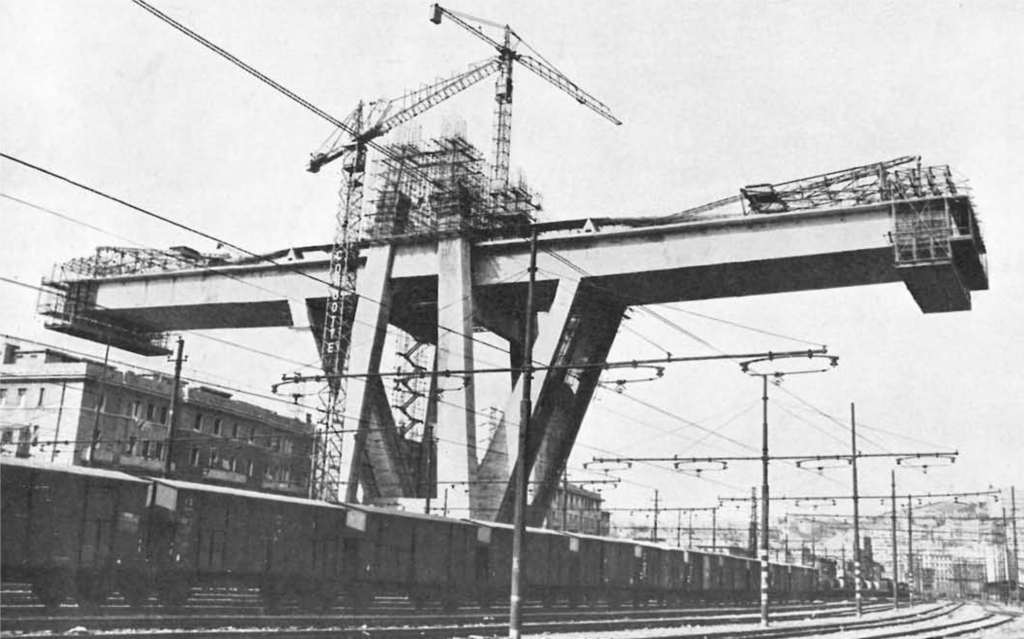
Due to the high degree of prefabrication and the cantilever construction, the Polcevera Viaduct could be built very quickly. Since the plan approval by the railway operators took some time, the execution took longer than for the more than eight kilometre long bridge over Lake Maracaibo, which was built in a record time of only 40 months (!). Without the delays mentioned, however, the main spans could have been executed in only 23 months [1].

Moreover, the Polcevera Viaduct was an extremely economic and efficient structure that, for example, consumed just one third of the (then expensive) prestressing steel per square metre of bridge area as the Bendorf Bridge, which was built at the same time and with a comparable main span across the Rhine near Koblenz. Compared to the now completed new bridge designed by Renzo Piano, the resource consumption and greenhouse gas emissions of Morandi’s Polcevera Viaduct were significantly lower, despite its significantly larger spans: The replacing bridge is statically inefficient due to the static system (carrying a large part of the loads as single-span girders) and the cross-sectional design (much material in the area of the neutral axis). While the former can be justified by the required fast erection of the single-span steel girders, the purely formal design of the cross-section (which apparently should resemble a vessel) is hard to understand: a statically efficient, lightweight cross-section would have been much more economical and climate-friendly, as well as beneficial for the fast erection, and could certainly have been designed aesthetically, too.
Collapse
Almost exactly three years ago, on 14 August 2018, an approximately 250 m long section around the western pylon collapsed, killing 43 people. To the best of our current knowledge [2], the collapse was triggered by the rupture of a stay cable, which led to the collapse of the entire pylon with the associated part of the superstructure, including the adjacent hang-in girders. The stay cable, which was designed as a prestressed concrete tension member, broke near the upper anchorage due to severe corrosion caused by the inadequate and partly even missing injection of the ducts in this area.
Weaknesses of the structural concept
After this tragedy, a number of professionals heavily criticised the concept of the bridge and Riccardo Morandi as engineer. Some of the criticisms made are simply wrong, and in part show a lack of expertise of the critics. For example, it was argued that the concept of the bridge was generally weak, which would be evident from the fact that only three such bridges had been built worldwide. In reality, there are many more such bridges – designed both by Morandi and by other designers – especially in Germany, where they are known as “Zügelgurtbrücken”. More specifically, it was criticised that the pylons were far too stiff, necessitating many expansion joints – apparently unaware of the fact that multi-span cable-stayed bridges require either stiff pylons or a very stiff superstructure [3]. Also, the design of the stay cables as prestressed concrete tension members rather than bare steel was criticised, without realising that Morandi had deliberately chosen this solution, since post-tensioning of the concrete resulted in about five times higher stiffness than the prestressing steel alone would have provided.
Such arguments, which are obviously wrong for experts, unfortunately find their way into the news after all major loss events that interest a broad public: Journalists working for the daily press leave no stone unturned to publish pointed statements by experts on causes and guilty parties as quickly as possible. However, these statements rarely come from truly competent experts because these are aware that without detailed knowledge of the object and the course of the collapse (which takes weeks or months), one can only speculate about the causes.
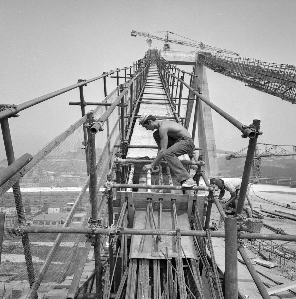
A point of criticism, which is basically valid, relates to Morandi’s underestimation of the long-term effects of concrete, especially creep. With today’s calculation methods, we can fairly well determine that a large part of the prestressing of the stay cables of the Polcevera viaduct had been lost over time. This caused the concrete to decompress and eventually crack, as actually observed in various inspections of the structure’s condition. These cracks – going along with an alternating dry-humid environment directly at the prestressing steel – presumably accelerated the corrosion of the prestressing steel of the stay cables. The long-term effects further caused excessive deflections of the superstructure, which impaired the driving comfort.
Furthermore, in a number of aspects, the bridge’s structural concept indeed did not meet the current state of the art, particularly regarding robustness: Obviously, the consequences of the failure of a single stay cable of the Polcevera Viaduct were disproportionate. Modern cable-stayed bridges, by contrast, are designed such that individual stay cables can fail without consequences for the structure. In addition, modern stay cables are protected against corrosion by multiple measures and designed such that damage is detected early and affected strands can be replaced. In the case of the Polcevera Viaduct, on the other hand, the concrete cover was very small and the prestressing steel was only partially protected by ducts. In addition, from today’s point of view, the chosen diameter of the ducts was too narrow for reliable grouting (which was anyway highly challenging due to the large height of the pylons). Due to corrosion damage, the stays of two of the three pylons were strengthened already in 1993 – however, the western pylon, where corrosion had progressed the least at that time, was left in its original state and therefore collapsed in 2018.
Assessment
When judged from today’s perspective, the structural concept of the Polcevera Viaduct indeed had weaknesses. So was Morandi no pioneer of bridge design, but rather a bad engineer – as some critics claim? My opinion here is obvious: it is unfair to judge a structure built more than half a century ago by today’s standards. When Morandi designed his bridges, they were primarily evaluated by their cost and construction time – and in these respects, the Polcevera Viaduct could hardly be topped.
Robustness, on the other hand, simply was no priority design goal back then, so that deficits in this respect are the rule rather than an exception for structures from that time. As an example, consider statically determinate truss bridges, which were common in those days, especially in North America: If a single truss member or a gusset plate fails, the entire bridge collapses – as unfortunately occurred in 2007 with the Interstate 35W bridge over the Mississippi (built in 1967 like the Polcevera Viaduct).
Many bridges from that time also have problems with durability, as very small concrete covers were common. Serious corrosion damage also occurs in bridges by indisputably outstanding bridge designers, such as the Crestawald Bridge by Christian Menn. However, one can hardly blame the project authors, as the problem of corrosion by chloride ingress was largely unknown at that time. It is rather astonishing that the owners of the Polcevera viaduct, despite clear signs of severe corrosion damage, did not take any measures to strengthen the western pylon – analogous to the strengthening of the other pylons 25 years before the collapse.
There remains the underestimation of the long-term effects of concrete, which even led one critic to claim that Morandi had good intuition but not much practice in calculation (“aveva grandi intuizioni, pero non grande pratica di calcolo”). This criticism is completely misplaced: it is clear from Morandi’s publications that he was also a master of his discipline in terms of analysis. His underestimation of creep redistribution was rather due to the fact that this phenomenon had simply not been sufficiently researched at the time of the Polcevera Viaduct project [4,5].
If one judges his bridges in the context of the time when they were designed and built, Riccardo Morandi undoubtedly remains the pioneer of bridge design that he was recognised as before the Genoa tragedy. However, the fact that his bridges are not to be measured by today’s standards does not mean that we should apply different standards to the assessment of structural safety for existing structures than we do to new ones: It is true that the requirements for serviceability can be reduced and actions as well as building material parameters can be updated, since they are known (in contrast to new structures). However, a higher risk of collapse is unacceptable. If such an increased risk is identified when examining an existing bridge, detailed analyses, strengthening measures or load restrictions are mandatory – as costly and/or unpopular as they may be.
In this respect, bridges differ from cars: if you drive a vintage car built in 1967 – for example, one of the Alfa Romeo GT1300 Junior on the blog entry’s cover photo – you accept that your vehicle has neither ABS nor airbags, and not even a dual-circuit braking system (which Alfa Romeo only offered in 1968, with the 1750 GT Veloce). It would hardly occur to anyone to impose the same standards on such a vehicle as on a modern car, or even retrofit modern safety systems.
Walter Kaufmann
Comment this post on LinkedIn or Instagram
References
[1] Morandi, R.: “Il Viadotto Polcevera dell’Autostrada Genova-Savona,” L’Industria Italiana del Cemento, No. 12, 1967, pp. 849– 872.
[2] Nutini, A.M, Rapporto della giudice per le indagini preliminari, 22.12.2020, 476 pp.
[3] Virlogeux, M., “Recent evolution of cable-stayed bridges,” Engineering Structures, Vol. 21, 1999, pp. 737–755
[4] Einfluss von Kriechen und Schwinden des Betons auf die Schnittgrößen und Spannungen, TH München, 1966
[5] Trost, H., “Folgerungen aus Theorien und Versuchen für die baupraktische Untersuchung von Kriech- und Relaxationsproblemen in Spannbetontragwerken”, IABSE Symposium Madrid, Vol. 5, 1970
Link zur deutschen Version: Internationaler Austausch während der Pandemie
There are many benefits that the presence of exchange researchers within our group can bring. According to Dr. Jaime Mata Falcón, working every day with foreign researchers is the best way to keep our minds and research horizons open. We are getting used to a global life and economy. An international exchange of research ideas and methodologies also provides a huge potential for synergies and progress. Publications are the most classical way of communication in research. Although they are an essential sharing step, publications tend to be impersonal and do not foster a high dialogue and interactions with our peers. Working together with foreign exchange researchers for some time builds a common understanding, both at the personal and professional level, which allows going into deeper interactions. This is an excellent opportunity to disseminate our ideas more efficiently, learn new ones, and set up longstanding collaborations. While we are getting used to work and interact virtually, I am convinced that these outcomes can only be achieved when one has the opportunity to work face-to-face for some time and learn about the other person and its culture.
Unfortunately, the ongoing Covid-19 pandemic has difficulted the interaction with foreign researchers spending some time with us. To get more insight into this topic, three exchange researchers share in this post their professional and personal experiences and how both have been affected by the pandemic.
Tell us about yourself!
I am Tobias Huber from Vienna, Austria. I am 32 years old and I work as a postdoctoral researcher in structural concrete. I have finished my doctoral studies at the Technical University of Vienna in 2019. My thesis is about the structural behavior of old concrete bridges. In the last years, my research focus lies on finding new ways for faster and sustainable construction. Besides research, I love to travel the world, play soccer and I am a passionate Vespa-driver.
My name is Laura Esposito and I am 28 years old. I come from Italy and I got my Master degree in Structural and Geotechnical Engineering at the University of Naples Federico II in 2018. After graduation, I decided to continue my career at the university with my doctoral research project: Innovative Structures obtained through the implementation of 3D printing technology in the construction industry. The doctoral research allows me to investigate very innovative topics and discover how much automation technologies are becoming crucial in all areas, including civil engineering.
My name is Lisbel Rueda García and I am 29 years old. After finishing my master’s degree in Civil Engineering at the Polytechnic University of Valencia UPV (Spain) in 2017, I enrolled as a PhD Student in Construction Engineering. My research focuses on the shear behaviour of concrete composite beams, although I have been also involved in concrete structures seismic reinforcement and repair.
What are you doing at ETH Zurich?
(Tobias) I work at the NCCR dfab project, which is an outstanding Swiss research initiative for digital fabrication in architecture and construction. In an interdisciplinary team, we are finding ways of integrating 3d-printing of formwork for reinforced concrete structures. With this robot-granted freedom of shape, it is possible not only to lower material costs and labour of formwork making but also to optimize the structural elements. This results in lower material consumption. We will try to show this benefit by building a floor-slab demonstrator.
(Laura) During my doctorate, I had the opportunity to join formative and exciting experiences around Europe. At ETH Zurich, I focus on reinforcement strategies and their effectiveness in 3D concrete printed structures, together with my Italian tutor (Costantino Menna) and my tutor at ETH (Jaime Mata Falcón). Me and Lukas Gebhard (an ETH doctoral student currently at my home university) are working together, sharing experimental results, technical knowledge and know-how. The possibility for an actual exchange with an ETH researcher was a key reason for doing my exchange. Furthermore, this experience allows me to collaborate with one of the leading universities emerging in the scientific research on Digital Fabrication.
(Lisbel) PhD grants funded by the Spanish Ministries might include extra help for supporting stays abroad to promote collaboration with a different university in the research project and the professional and personal development of the doctorate student in another university. Thanks to this help, I am currently at ETH for three months for numerically modelling the specimens I tested at the UPV with the software IDEA StatiCa Detail, which is based on the Compatible Stress Field Method (CSFM) developed at ETH.
Why did you choose ETH Zurich?
(Tobias) At the beginning of my doctoral studies back in 2016, I had the chance to join a workshop about shear in concrete structures from the fib held at ETH Zurich by the chair of Prof. Kaufmann. I got to know Prof. Kaufmann and his team, as well as the impressive structural laboratory at ETH. I knew back then, if I ever got the chance to do research abroad, ETH Zurich and the IBK would be my first address.
(Laura) My choice is undoubtedly linked to ETH Zurich being one of the leading universities on Digital Fabrication. Scientific research at ETH is advanced thanks to the many groups working in cutting-edge laboratories (such as the Robotic Fabrication Lab). Additionally, I have the opportunity to improve my research in one of the hot topics in my field: how to reinforce 3D concrete printed structures.
(Lisbel) Already in a pre-pandemic situation, to find a place in which you could work on something that improves your own research and to have guarantees of being supported by a supervisor was not easy. With the Covid pandemic, finding the proper place with so many movement restrictions was even harder. Knowing someone at ETH (in my case, Dr. Jaime Mata Falcón, who belonged to my home university) can facilitate this search. This, in addition to the fact that it is one of the most prestigious universities in civil engineering, made ETH the perfect destination.
What is the main difference to your home university?
(Tobias) The group of Prof. Kaufmann is about three times the size of our Institute in Vienna, when it comes to the number of research assistants working there. So they have a lot of variety in their research topics, which leads to very fruitful scientific discussions. This is encouraged in many ways. For example, they organize a biweekly format called Journal Club, in which interesting papers are discussed together. This gives me a lot of new aspects for my own work.
(Laura) Everything at ETH is really big, such as the number of laboratories and lab machines available. Last but not least is the number of people working in the Prof. Kaufmann group and the number of topics addressed. These factors are fundamental in the scientific research field in which experimental activities, continuous exchange, and discussion are the core.
(Lisbel) Definitely, where I have noticed the greatest difference, and probably what I will miss the most, is in the team atmosphere. Kaufmann’s Group is a large research team in which a sharing perspective is encouraged. The interaction between people and teams, something quite common in private companies, is not always observed in academic research. A doctorate is a relatively long stage in our lives. It is enriching, both from the personal and professional levels, to carry out this stage in a team atmosphere. Moreover, sharing of ideas creates important synergies.
How did the pandemic influence your time at ETH Zurich?
(Tobias) My time here started officially in April 2021. Since the number of Covid-cases in Vienna had risen in February/March I had to spontaneously travel a bit earlier as planned to Zurich to avoid Quarantine. The restrictions and the number of cases in Zurich were less compared to Austria, which made life also quite relaxed. Luckily, I was allowed to spend some time in the office. Moreover, the Kaufmann group organized virtual coffee-breaks, which helped a lot to get in touch.
(Laura) I am very happy to be here, even if this is not an easy phase: all of us are now experiencing the Covid pandemic, which is influencing our way of leaving. Nevertheless, with protective safety measures, I am able to enjoy the campus life, research and laboratory activities, and the wonders of this country.
(Lisbel) Of course, social life, at and outside work, has been limited by the pandemic. Even so, the fact that the team atmosphere is something that I liked about my stay here means that the Group has been able to incorporate new technologies to work. Despite not seeing many of the colleagues in person, regular meetings are held to discuss work and non-work issues, which allows you to meet workmates and learn from them despite the existing limitations.

What do you take home from this collarboration?
(Tobias) All these experiences I had and new things I saw at ETH are now packed in my “scientific backpack”. I think this will overall enhance my future research. My goal is to write at least on paper about my experiments here. What I think is more important is this new network I was able to grow here. I think this will lead to future collaborations between ETH and TU Wien.
(Laura) The foreign experiences are really formative from professional and personal sides. Knowing other cultures, lifestyles, foods, or traditions is essential to grow, discover, and appreciate your own and new costumes. Here at ETH Zurich, this is easier since it is like a little city, in which students from all parts of the world come to learn and share.
(Lisbel) This collaboration has allowed me to meet new people involved in my field of research, which is appreciated in times of scarce conferences in which to network. In addition, without the intention to underestimate my home university, since I consider that the knowledge level acquired at the UPV has nothing to envy other highly prestigious universities, having been at the ETH will enrich my CV. On the other hand, the work carried out during this stay lead to very interesting research results, as well as having created a connection between my home university and the ETH that could favour future collaborations.

What was unique during your time at ETH Zurich?
(Tobias) The very helpful and nice people here at IBK and generally in Switzerland. I would be glad to stay in contact with my new colleagues over the years, not only for research aspects.
(Laura) The link between Zurich city and the green spaces. Even here, on the Hönggerberg hill, there is a fantastic contrast between ETH’s innovation and technology and the rural environment outside.
(Lisbel) The people I have met here and the amazing places I have visited around Switzerland. Although my short stay, I feel I have made friends for life with whom to celebrate my future doctor’s degree either in Zurich or in Valencia.
Which cultural differences were you not aware of?
(Tobias) I already knew that fondue is a national dish in Switzerland and I enjoyed it very many times. What I did not know is that it is mostly eaten in the cold time of the year. So whenever I told a Swiss that I ate a Fondue, they were arguing that actually, it’s not the right time of the year, except in Wallis ;-).
(Laura) People can enjoy free time and outdoor spaces as soon as possible, even during working days after office hours: hikes, walks around the lake, recreational activities are perfectly integrated with everyday life.
(Lisbel) The passion for hiking and how fit people are for that, which is completely understandable with these impressive landscapes; the lunch time around 12am instead of 2pm, which in the end I have found much better; and that Swiss people are not very open at first but, after just a single plan outside work, the relationship completely changes to a really good friendship.

Tobias Huber, Laura Esposito and Lisbel Rueda García
Link zur deutschen Version: Der Weg zur automatischen Rissmessung in Versuchen zum Tragverhalten von Beton.
Almost five years ago, as part of a Master’s project thesis, I received the opportunity to develop first methods for a crack measurement tool for the evaluation of concrete tests. The aim was to automatically detect cracks and measure their width and slip from the surface deformation measurements obtained by digital image correlation. My supervisors Prof. Dr. Walter Kaufmann and Dr. Jaime Mata-Falcón had already worked out the first ideas and concepts at this point and some test data were also available. After completing the project thesis, the tool was continuously refined and increasingly used in the analysis of our experiments. The procedure showed great potential, so that today it is freely available as open-source software under the name ACDM (for “automated crack detection and measurement”). The graphical user interface allows an easy application and also other research institutes have started using this tool. This blog post is about the process leading to today’s ACDM, its importance in experimental research and the most important elements that helped the tool to leverage.
Why are crack measurements in experiments so important?
To better understand the load-bearing behaviour of concrete elements and to be able to develop and validate models, structural tests are necessary for which the cracking behaviour is accurately assessed. For example, the shear force that can be transmitted across cracks due to aggregate interlock is strongly dependent on the roughness of the crack surface and the crack width. Such properties must be recorded accurately in order to allow validating aggregate interlock models. In many cases, large-scale tests are required to obtain results that are representative of real-life structures. However, such large-scale tests are very laborious and generally show a complex crack pattern, where the exact crack locations cannot be predicted. Various instrumentation techniques have already been developed for measuring cracks, but their applicability is often severely limited. This is mainly because the resolution and accuracy of the measured crack kinematics, i.e., crack width and sliding, are usually not sufficient to assess the actual load-bearing and deformation behaviour of the material reliably. The accurate measurement of cracks with a high resolution is therefore crucial but is a major challenge.
How have cracks been measured in the past?
Until some time ago, the standard procedure for measuring cracks in experiments consisted of temporarily stopping the experiment at selected load or deformation states and measuring relevant crack widths by hand using crack rulers or crack magnifiers directly on the surface of the specimen. However, this manual measurement method is prone to measurement errors and is also very time-consuming, especially for large-scale tests with a large number of cracks. Furthermore, for elements with low deformation capacity, relevant measurements close to the failure are usually missing due to the risk involved in terms of safety for the personnel.
Alternative measurement techniques – such as the use of DEMEC, NDI or LVDTs (“linear variable differential transformers“) – improve the accuracy of crack measurements as well as the temporal resolution, but are still limited to a few predefined crack locations and therefore hardly applicable to complex crack patterns where the exact crack locations usually cannot be predicted.
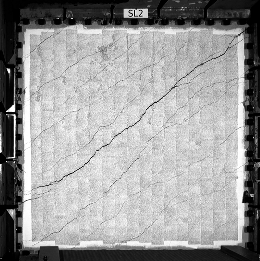
What are the benefits of digital image correlation (DIC)?
Digital image correlation (DIC) is a camera-based deformation measurement method for surfaces in which the deformation of a pattern consisting of random points is measured by correlation algorithms. From the full-field and high-precision displacement measurements obtained in this way, surface strains of the component can also be calculated using relatively simple procedures. Compared to conventional measurement methods, DIC provides quasi-continuous measurements (spatially and temporally), and thus offers new possibilities for very detailed and reliable assessment of the crack behaviour in laboratory tests.
Although DIC is already used in many research institutions to measure crack openings and slidings, the results are usually only determined at a few discrete points using manually set extensometers, which means that much valuable information is lost. Such manual procedures are also hardly applicable to large-scale tests with complex crack patterns. The DIC data volumes generated in large-scale tests are extremely large and can therefore only be efficiently processed into usable results by automatic procedures. In addition, the crack openings and slidings must be determined through virtual reference points that are somewhat separated from the actual crack line in order to obtain bias-free measurements. This leads to the fact that even slight rotations of the specimen have to be taken into account (especially for crack slip measurements), which considerably complicates the procedure. However, it must be mentioned here that the latter point applies to all crack measurement methods in which crack lip displacements are not measured directly but through reference points that are just slightly separated from the crack line (hence, also for crack measurements using manual DIC extensometers but also e.g. when using DEMEC, NDI or LVDTs).

Concept of displacement measurements based on DIC. 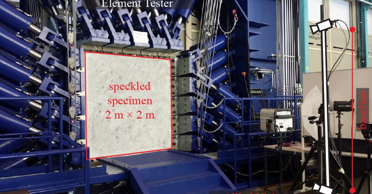
DIC setup in the Large Universal Shell Element Tester (LUSET) with two cameras to measure 3D displacements. Image credits: Mata Falcón et al. 2020.
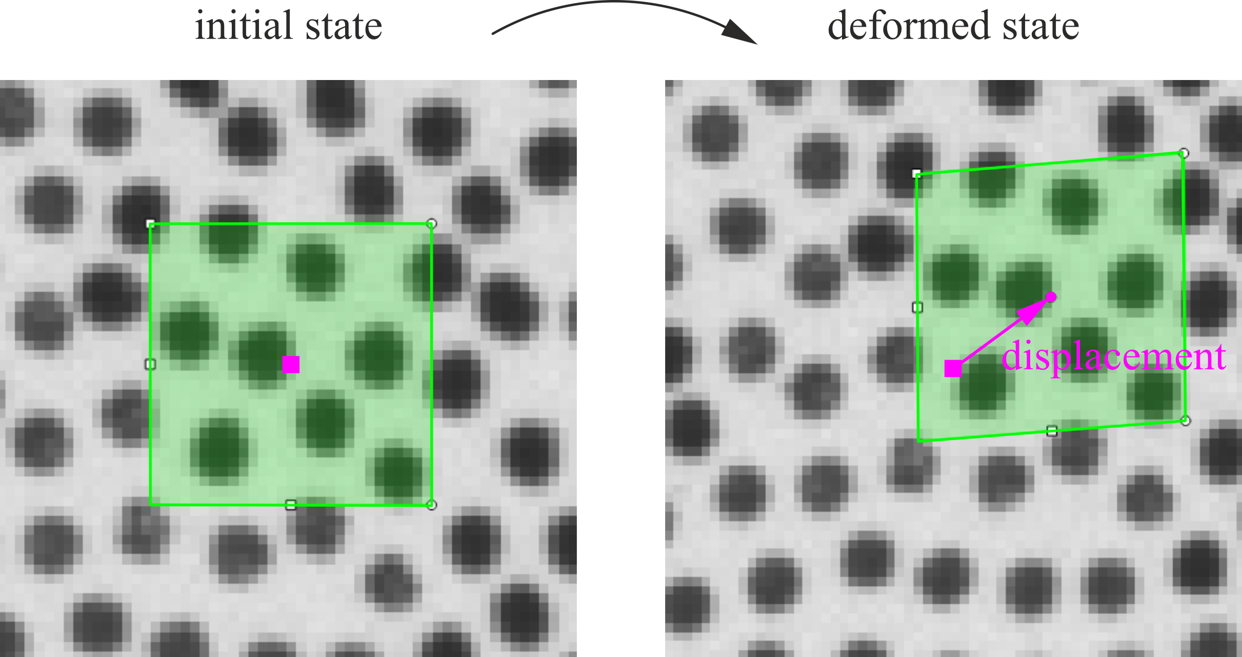
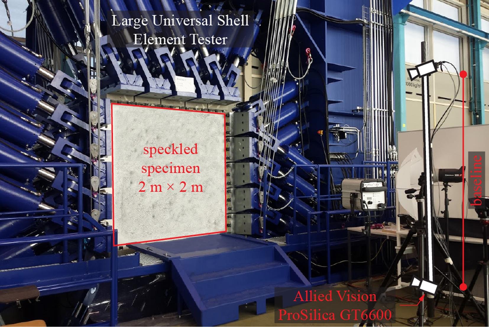
To use DIC efficiently for assessing the crack behaviour in concrete tests – which would not be possible with this accuracy and resolution by other known instrumentation techniques – first steps towards today’s fully automated DIC-based crack detection and measurement tool “ACDM” were taken in our research group some years ago.
What have been the first steps in the development of ACDM?
From the beginning, the basic concept of ACDM was to use the relationship that the local surface tensile strain at cracks theoretically becomes infinitely large. However, due to the finite resolution of the DIC and the fact that the strain field is often filtered to reduce the measurement noise, finite tensile strains result at the cracks. The size of the calculated principal tensile strain is then related to the crack kinematics, i.e. the crack openings (deformation perpendicular to the crack inclination) and the crack sliding (deformation parallel to the crack inclination). Thus, we sought a method to extract cracks at locations with high principal tensile strains. A first solution was to determine zones with high strains and then thin them into crack lines (as crack skeleton) by well-established morphological operations.
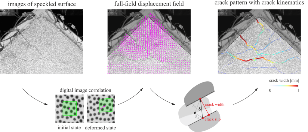
The detected crack lines have the great advantage over individual independent crack points that the local crack inclination can be calculated for each crack point, which is needed, among others, to determine the crack kinematics. The crack lip displacements were calculated in a first step using two reference points (at each side of the crack) in order that – as already mentioned – local rotations of the specimen could be taken into account.
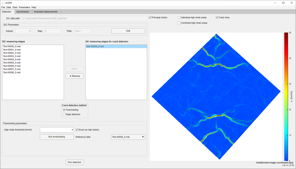
How was ACDM refined into a fully automated software?
From the beginning, the methods were integrated into a graphical user interface to facilitate the use of the tool. In tests with a relatively simple crack pattern, it quickly became apparent that ACDM provides very accurate results of crack locations and crack kinematics. For more complex crack patterns, however, problems with biased results in areas close to crack intersections were observed, where the method failed. Therefore, in a next step, the crack detection procedure was revised. Instead of zones with high strains being thinned to crack lines, in today’s version of ACDM the crack lines are extracted directly as edges in the strain field. In addition, the number of reference points was increased in the calculation of crack kinematics and an algorithm was developed that improves the reliability of the results.
ACDM is available to the public as open-source software at https://gitlab.ethz.ch/ibk-kfm-public/acdm. In various experiments of our research group and especially in our large-scale tests in the Large Universal Shell Element Tester (LUSET), ACDM has already been successfully applied and could thus contribute to relevant new findings on the load-bearing behaviour of concrete. For example, Alexander Beck and Demis Karagiannis tested 2.0 x 2.0 large-scale concrete panels in LUSET as part of their recently published doctoral theses, using ACDM in the evaluation of the test results. The obtained information on the crack behaviour was of central importance in the development and validation of their mechanical models. But ACDM also found favour outside ETH and has already been used in various studies to evaluate experiments.
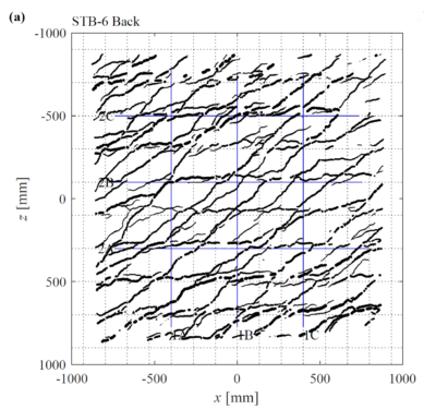
rack pattern of a panel test in LUSET subjected to combined shear and bending loads. Image credits: Karagiannis 2021. 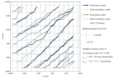
Crack pattern of a shear panel test in LUSET. Image credits: Beck 2021.

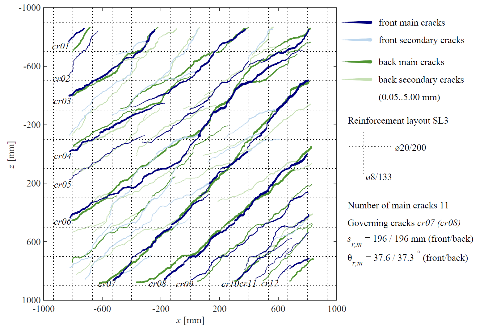
To ensure that this continues in the future, we are constantly improving ACDM. One goal we have been pursuing for a long time, for example, is the real-time measurement of cracks using ACDM, which would enable us to conduct experiments by controlling crack widths or crack slidings (which, for instance, is important in experiments with fibre reinforced concrete elements). We also see potential of ACDM in monitoring of existing structures for early damage detection. Corresponding investigations are currently being carried out.
Nicola Gehri
Link zur deutschen Version: Schubtragverhalten von schwach bewehrten Stahlbeton-Scheibenelementen
In developed countries, a huge number of ageing infrastructure objects need to be reassessed to ensure their structural safety. However, current assessment methods for analysing the load-carrying capacity of existing structures are in many cases not sufficient as they are typically based on the same models as the methods used in the design codes for new structures. In particular, the estimation of the shear strength is often deficient due to low transverse reinforcement ratios which were possible due to the ancient code provisions. In my dissertation, which I successfully defended in February, I tried to improve the comprehension of the load-deformation behaviour of reinforced concrete membrane elements with very low amounts of and without vertical reinforcement subjected to in-plane shear and normal forces.
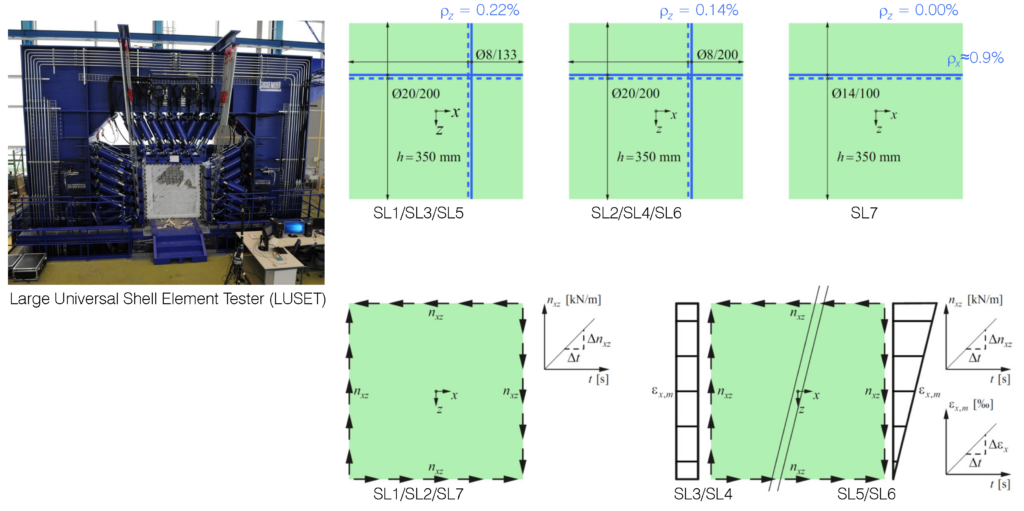
To this end, an experimental test campaign consisting of six large-scale membrane elements with very low amounts of vertical reinforcement of ρz=0.14…0.22%, and one uniaxially reinforced membrane element was carried out. Three panels were tested under pure in-plane shear and four panels were tested under in-plane shear with imposed longitudinal strain with and without gradient over the height of the specimens. The tests were conducted in the newly developed testing facility Large Universal Shell Element Tester (LUSET). The applied modern measurement techniques, namely digital image correlation (DIC) and fibre optic (FO) strain measurements, yielded very valuable and comprehensive data of the full-field deformations and the crack patterns on the concrete surface, and of the continuous strains along the embedded reinforcing bars.
The test results were compared to theoretical models in terms of the global load-deformation behaviour of the tested membrane elements, but also in terms of cracking behaviour and aggregate interlock, i.e. the stress transfer across the cracks in the membrane elements. The model predictions of the cracked membrane model with fixed interlocked cracks (CMM-F), which was originally developed by Professor Walter Kaufmann, were excellent for the panels with very low amounts of vertical reinforcement. The CMM-F, in particular using the rough crack model (RCM) as aggregate interlock model, yielded very good predictions. The RCM is a purely empirical aggregate interlock model, which was fitted based on numerous tests. The CMM-F using Walraven’s more mechanically based two-phase model (TPM), which is the most widely used aggregate interlock model, lead to conservative predictions. This is fortunate in terms of the application of models based on the TPM in design practice (e.g. the shear provisions for members without shear reinforcement in the SIA 262). Another important finding of the experimental campaign regarding the design practice was the confirmation of the well-established recommendation to use a minimum reinforcement ratio of ρz=0.2% for normal strength concrete. It is advised against the tendency to lower this value as e.g. done in the fib MC 2010 or the SIA 262.
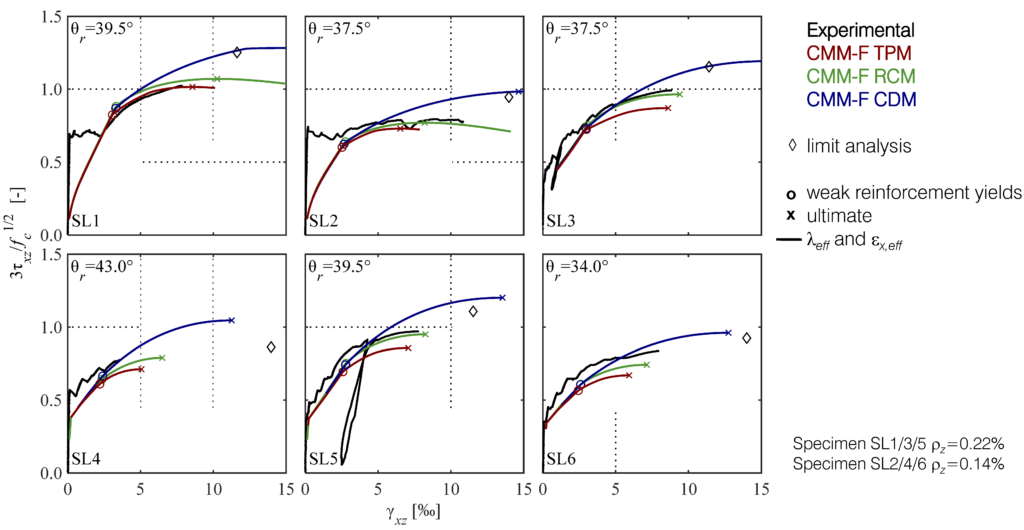
It could also be shown in the large-scale panel tests that the available aggregate interlock models from literature only work well in an average sense, as the model predictions of the SL tests were very good, but the aggregate interlock stresses calculated from the measured crack kinematics varied widely. Hence, the available aggregate interlock models are not suitable to predict the stress state of an arbitrarily shaped crack in a structural member. Additionally, crack spacings, inclinations and shapes are hardly predictable due to many local influences such as internal stress restraints, the variation of the tensile strength within the specimen, reinforcing bars running below the concrete cover and the distribution of aggregates in the concrete.
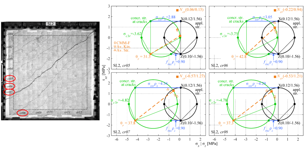
Alexander Beck
Link zur deutschen Version: Umweltfreundliche Betonbauten?
Concrete – Foundation of urban civilisation
Concrete was indispensable for industrialisation and the development of our urban civilisation and is by far the most widely used building material today: around 15…20 billion cubic meters of concrete are cast annually, i.e. more than two cubic meters per world inhabitant(1). Concrete is this widely used because it unites good mechanical properties(2) with high durability(3) and fire resistance, combined with worldwide availability at low cost. The latter two advantages are often overlooked but are probably the most critical factors for the widespread use of concrete.
(1) Exact figures are not available. The estimate is based on the annual worldwide production of 3.99 billion tons registered by Cembureau (key figures Cembureau), extrapolated according to the procedure of the Cement Sustainability Initiative assuming 300 kg of cement with 70% clinker content per cubic meter of concrete. According to FSKB statistics, 15 million cubic meters of ready-mix concrete are supplied annually in Switzerland, which corresponds to an annual concrete consumption of around 2.5 cubic meters per capita given the 75% share of ready-mix concrete.
(2) Concrete has high compressive strength but fails in a brittle manner when subjected to minor tensile stresses. The invention of reinforced concrete, in which a reinforcement – usually in the form of reinforcing steel – resists tensile forces, was therefore essential to the success of concrete structures. On the other hand, the concrete ensures that the reinforcement heats up only slowly in the event of a fire, thus providing a high level of fire resistance. Reinforcing steel – around 1.6 million tons are used in Switzerland every year – is today produced almost exclusively from scrap metal.
(3) Thanks to the hydraulic properties of the cement, concrete is durable and even hardens underwater. The service life of weathered unreinforced concrete is therefore almost unlimited, as demonstrated, for example, by the Pantheon in Rome. This also applies to structural concrete, as long as the reinforcement does not corrode. If corrosion is an issue depends primarily on exposure: While there are no concerns in dry interiors, structures exposed to moisture and chlorides may need to be repaired after a few decades. Compared with most other building materials, however, the durability of reinforced concrete is very high even under such exposure.
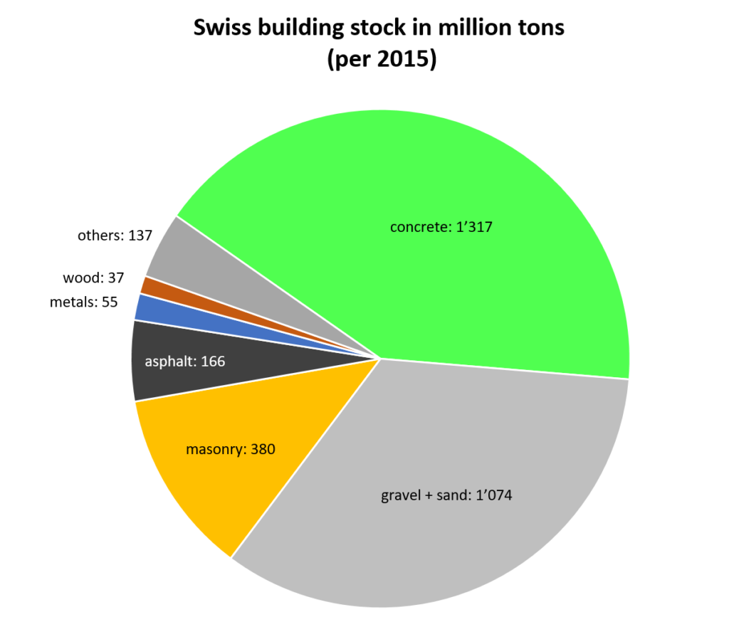
High resource consumption and greenhouse gas emissions
Obviously, the widespread use of concrete as a construction material is accompanied by high resource consumption, even though this can be somewhat improved by reusing demolished concrete as recycled aggregate for new concrete. In addition, the cement used as the binder in concrete contributes around 5…8% to global greenhouse emissions, depending on the calculation method(4). Therefore, in the light of climate change, calling for concrete to be replaced by other building materials, in particular wood, seems the obvious thing to do.
(4) The production of Portland cement (aka clinker) by calcining limestone and marl releases around 470 kg of CO2 per ton. Heating the raw materials to the temperature of approx. 1450°C required for calcination causes a further 100…500 kg CO2 per ton of clinker (depending on the fuel used). The high cement consumption of 3.99 billion tons per year (key figures Cembureau) – in Switzerland alone 4.21 million tons (key figures cemsuisse) – results in correspondingly high greenhouse gas emissions.
Replacing concrete: A viable solution?
However, the substitution of concrete is only partially possible and, at least on its own, not expedient. On the one hand, concrete is de facto without alternative for many applications: basements of buildings, retaining walls, dams or tunnels in other materialisation are far from being equivalent to concrete in load-bearing capacity, durability and costs. On the other hand, alternative building materials can only cover a small part of the quantities of building materials required worldwide(5). Moreover, they cause correspondingly high greenhouse gas emissions when built in large quantities, which in most cases exceed those of concrete(6).
(5) For example, annual logging worldwide today is about 2 billion cubic meters, of which about 500 million are processed into wood products (FAO Global Forest Products Facts and Figures 2018). This amount is equivalent to a few per cent of concrete consumption. Even if this amount were to be significantly increased (to the extent that this is feasible with sustainable forestry), only a small portion of concrete could be substituted.
(6) Here, solid timber is an exception, but many wood-based materials do cause high emissions as well. For example, plywood emits around six times more CO2 per cubic meter than concrete (KBOB Ökobilanzdaten im Baubereich (KBOB Ökobilanzdaten im Baubereich).
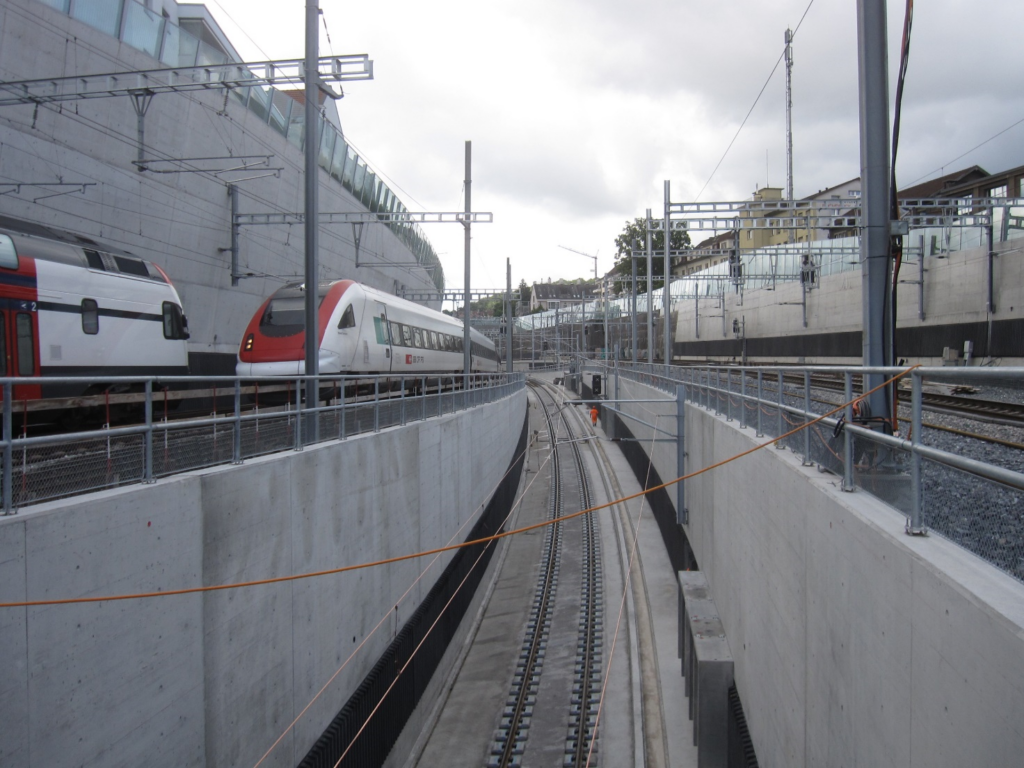
© dsp Ingenieure + Planer AG
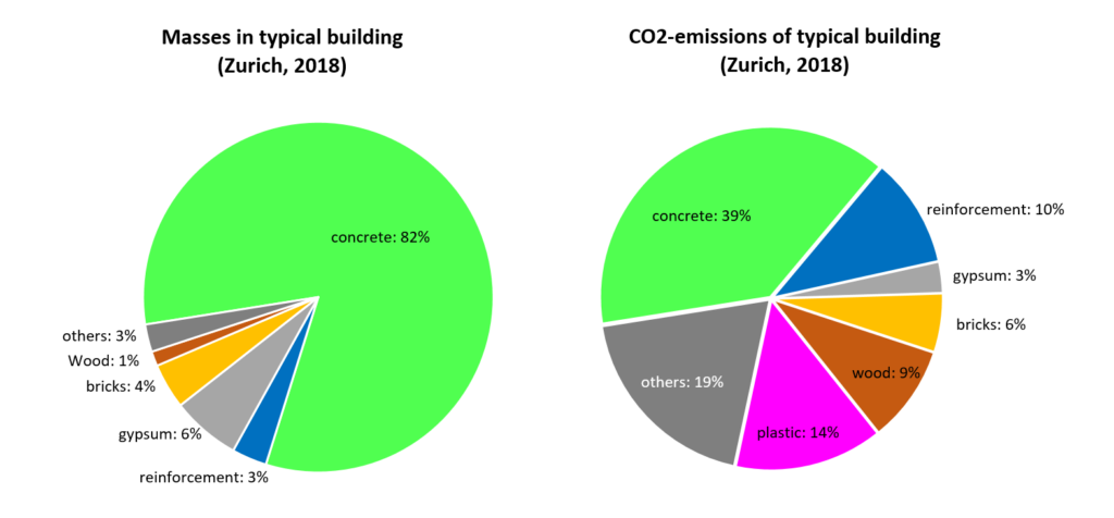
Therefore, if resource consumption and greenhouse gas emissions of the building industry are to be substantially reduced, concrete cannot simply be replaced. Instead, construction activity as a whole would have to be limited, combined with a transition to a circular economy. Such considerations are justified for industrialised countries: We already have a good infrastructure and can afford higher costs for its preservation, replacement or extension using alternative building materials – if necessary through incentive taxes to promote them. However, in developing and emerging countries, this is hardly realistic, and I find it presumptuous of industrialised countries to demand that these countries take such criteria into account when building their infrastructure or even ask for sacrifices. Bearing in mind that these countries today consume around 85% of the worldwide cement production (https://www.suedwind-magazin.at/zweischneidiges-schwert), replacing concrete is not really the solution.
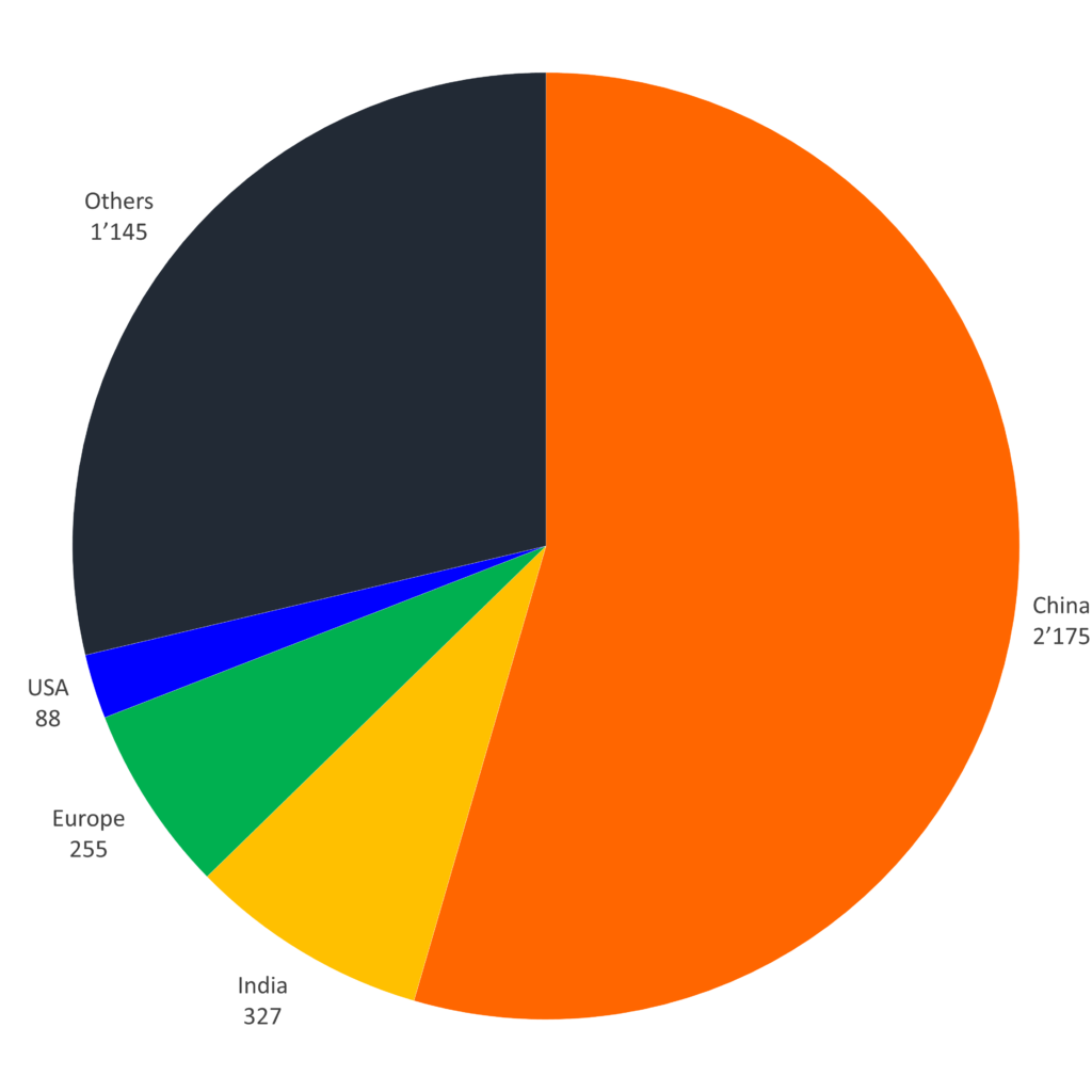
Environmental friendliness through structural efficiency
Rather, the goal must be to reduce resource consumption and emissions of concrete construction. To this end, Cembureau has developed the “5C” approach, which consists of the following five points:
- Clinker – reduction of fossil fuels used in clinker production
- Cement – reduction of the clinker content in cement
- Concrete – reduction of the cement content in concrete
- Construction – reduction of concrete consumption in buildings and structures
- Carbonation – increase carbonation
The first point is already largely implemented in Switzerland: Today’s Swiss cement industry uses more than two-thirds of alternative fuels for its energy needs. The clinker content in Swiss cement has also already been significantly reduced: The proportion of pure Portland cement, which was practically exclusively used until 1998, is now less than 7% (key figures cemsuisse). A further reduction of the clinker content in the cement is possible. However, the durability must not be impaired. For the latter reason, reducing the cement content in concrete is not straightforward either(7).
(7) Durability issues occur in concrete structures primarily due to reinforcement corrosion. The alkalinity of the concrete, which is ensured by the use of clinker, protects the reinforcement from corrosion. This must be taken into account when reducing the cement content and the clinker percentage in the cement for exposed concrete members.
Concrete buildings absorb 10-20% (depending on the calculation method) of the greenhouse gases emitted over their lifetime due to the carbonation of the concrete (CO2 uptake). This proportion can be increased, for example, through the targeted carbonation of crushed concrete granulate (https://www.aramis.admin.ch/Texte/?ProjectID=47360). An interesting alternative is to capture CO2 at an emission source and synthesise limestone from it, as the company Blue Planet is already doing. If such synthetic limestone is used as aggregate for concrete, concrete structures will absorb more CO2 in the future than is emitted by cement production. However, it is currently impossible to predict whether the process can be scaled up and operated economically.
Personally, I see the most significant potential in the reduction of concrete consumption, which can best be achieved by structural efficiency. Efficient structures transfer applied loads with low dead weight (and thus low resource consumption and emissions) in a material-appropriate way. This is where structural engineers can and must make their contribution to climate protection.
Due to low material prices and rising labour costs, structural efficiency has unfortunately all too often been neglected as a design goal in recent decades. Instead, simple structures that could be built quickly were favoured, even if they required considerably more material. In addition, minimum dimensions of concrete structures were continuously increased: In building construction to ensure sound insulation and to accommodate service ducts(8), and in civil engineering to ensure maximum durability(9). Here, the increasing pressure to reduce resource consumption and greenhouse gas emissions offers civil and structural engineers the opportunity to recover one of their very own areas of expertise and to restore the significance of structural efficiency to the status it deserves.
(8) An example of this are houses with controlled ventilation, as required to achieve the “Minergie” label. To be able to integrate the ventilation into the floor slabs, slab thicknesses are usually 26 cm. However, a much thinner slab would be sufficient from a structural point of view.
(9) The requirements for durability have been significantly increased due to experiences with corrosion damage to early concrete structures, which is undoubtedly justified: Premature replacement of a corroded structure is certainly not sustainable. However, the maximum durability requirements that many codes and clients today impose as a general rule on all structures should be questioned and differentiated, as they come at the expense of resource consumption and greenhouse gas emissions.
Efficient concrete structures
The most efficient concrete structures are undoubtedly anti-funicular arches and shells, which are lightweight and transfer applied loads primarily via compressive forces. However, this only applies to the final state. However, the conventional construction of such structures often requires very elaborate falsework and formwork, which significantly reduces their advantages
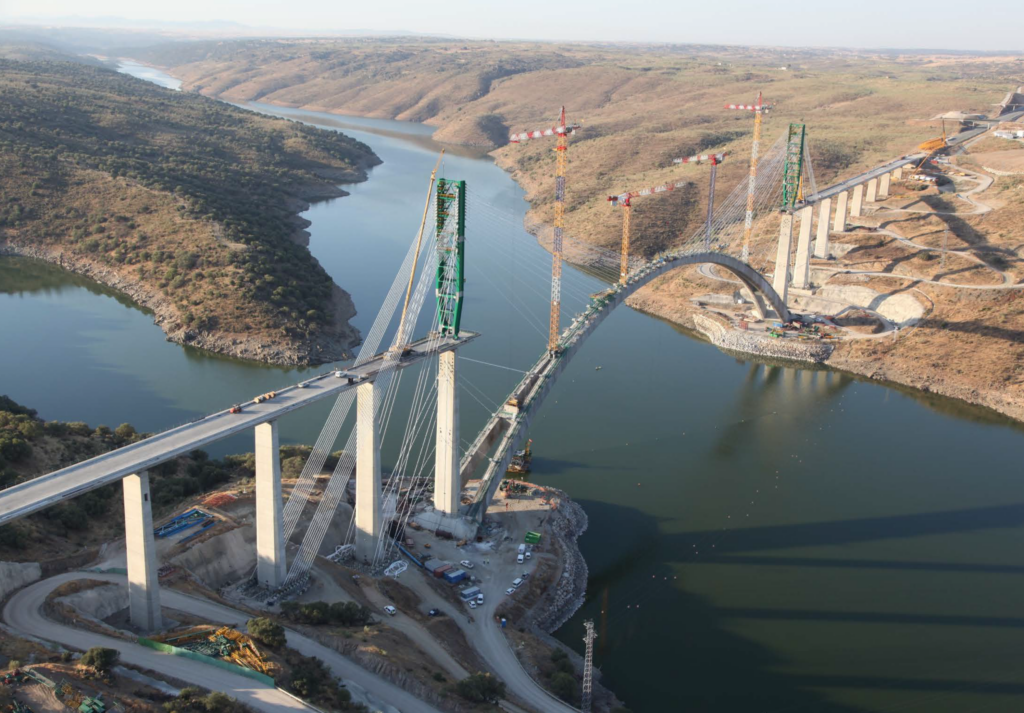
© Arenas & Asociados
Here, it is necessary to develop more efficient construction methods, which is, for example, a subject of current research in the NCCR dfab at ETH Zurich (https://dfab.ch/streams/lightweight-flexible-formwork). Such efforts are by no means new: for example, as early as 1892, J. Melan developed a system for constructing arches where a lightweight steel arch simultaneously serves as falsework for the concrete and its primary reinforcement. Today, arch bridges with spans of over 500m are being built in China using the “CSFT” (Concrete Filled Steel Tube) construction method based on the same principle (https://concrete.ethz.ch/brd/arch-bridges/).
By their curved nature, arches and shells are unsuitable for many applications, such as floor slabs, the most widespread application of reinforced concrete. However, even geometrically relatively simple structures can be structurally efficient if they are designed appropriately. There are some basic principles to be observed here that should be self-evident for structural engineers:
- Choose efficient structural systems: Continuous beams are much more efficient than simple beams
- Select efficient cross-sections: Profiled beams have much higher stiffness and resistance than rectangular cross-sections at the same weight
- Adapt girder height to load
- Consider construction process in design
For floors, ribbed, waffle and hollow core slabs are particularly suitable, typically enabling savings of more than 50% of the material compared with a solid slab. Here, as well, there are existing systems, such as standardised formwork for in-situ concrete coffered slabs and prefabricated hollow core floors. New possibilities are the subject of current research at the NCCR dfab at ETH Zürich.
Conclusion
Reducing resource consumption and greenhouse gases is imperative in view of climate change. However, replacing concrete with other building materials is only useful in a few cases, since the problem is not concrete per se but rather its widespread use: When other building materials are used in equally large quantities, they consume just as many resources and cause similarly large greenhouse gas emissions as concrete.
In fact, our buildings as a whole must become more environmentally friendly. By designing efficient structures, structural engineers can and must make a substantial contribution to climate protection. To ensure that such structures are also economic, the construction process must be part of the conceptual design process. Furthermore, we must develop construction methods enabling more complex structures to be built efficiently.
At our chair, we try to contribute by teaching the basics of efficient structural design and researching new fabrication methods.
Walter Kaufmann
Link zur deutschen Version: Lernen zu lernen: Digitale Lernapplikationen in der Stahlbeton-Vorlesung
Just as the basic principle of concrete construction has changed only slightly over the last hundred years, the structural concrete lecture seems to have remained the same since a few decades ago. The curriculum is based on a consistent application of equilibrium and a strong focus on mechanically consistent models, representing a tradition at ETH that Prof. Thürlimann and Prof. Marti had particularly shaped. This not only strengthens the competence in structural concrete, but also forms a good foundation for the education of young civil engineers in general. The awarding of the Golden Owl to Prof. Kaufmann for exceptional teaching by the students’ organisation of ETH also shows that our teaching is perceived as competent and authentic. Although we are convinced of our lectures’ content, we still see some potential for improvement – especially concerning the teaching methods and applied tools.
Digitalisation in teaching
Concrete has undergone some adjustments in its formula over time, and also our lectures have been adapted to meet today’s standards. Instead of a handwritten autography, the slides are now digital. Instead of working exclusively on the blackboard, the notes are now partly written on the iPad and projected. But is this mild digitalisation an innovation in teaching? The classical way of frontal lecturing seems to have no alternative when it comes to imparting knowledge. However, the wealth of information during a lecture is immense, and students do not always manage to absorb and directly process everything. The students often only start dealing with the subject matter much later, either when they are solving the colloquia and exercises or shortly before the exam, whose preparation consists of internalising “recipes” for certain types of tasks. Unfortunately, the understanding of the subject often becomes secondary. Of course, we as lecturers see ourselves as responsible here. So how can we improve teaching to give students easier access to the rather dry analytical methods?
Innovedum – «Advancing education at ETH»
“Innovedum” is a brand established by Rector Prof. Springman, which promotes “initiatives that contribute to the development of quality education at ETH in the long term”. This has already resulted in numerous innovative teaching and learning projects across various disciplines and with different approaches such as hands-on workshops or gamification of teaching content. So we also asked ourselves how new teaching elements could be introduced to foster critical thinking and self-initiative among students. In the structural concrete lecture, we mainly deal with the load-bearing behaviour of structures using limit states (e.g. at failure load). Although these rely on proper and mechanically consistent derivations, they are limited to isolated conditions with predefined parameters, making it difficult to fully grasp the non-linear behaviour of structural concrete. The new teaching material should offer both a dynamic representation of the results and the possibility to change parameters actively. This idea sparked the development of digital learning applications for the structural concrete lecture as part of a teaching project financed by the Innovedum Fund.
Virtual experiments and structural analysis
The majority of applications consists of virtual experiments, where elements and structures can be investigated under different loading types. There are examples where the current stress state under a given load is considered, but also applications where the load-deformation behaviour with increasing load can be followed. It was vital for us that the students can change the input parameters as freely as possible. The continuous tracking of the output parameters ensures a better understanding of the transitions between the analytically derived limit states. A good example is the interaction of bending and normal force in reinforced concrete columns. In the lecture, we learn how to determine the stress state in the reinforced concrete cross-section based on the strain state and the material laws. We can thus construct a linearised envelope for the ultimate load in the M–N space with just a few characteristic pairs of bending moment and normal force. The change in stress and strain states between these characteristic points appears relatively complex due to the non-linear relationships. In terms of geometry, this corresponds only to a rotation of the strain plane, which can be nicely shown in a dynamic illustration. By changing the acting normal force using a slider, one can observe the changing strains and stresses at one’s own pace. For example, it is easy to see that at the point of maximum bending moment, the governing strain no longer occurs in the reinforcing steel but in the concrete when the compressive normal force is further increased.
Not only the load can be changed, but also the geometry and reinforcement, which – for instance – can show that a doubling of the reinforcement content does not lead to a doubling of the bending resistance for a given normal force. These findings may seem trivial. However, we are convinced that even such simple animations and the small eureka moments can contribute considerably to the understanding and foster the students’ curiosity for the effective behaviour of structural concrete, which goes beyond the calculation of limit states with the help of rigid formulas.
The applications are also helpful for problems that we solve graphically but are relatively time-consuming to work out by hand, especially if multiple states have to be considered. A good example is the strut-and-tie model, where the moving point load across the beam creates different inclinations of the stress fields and their influence on the internal load-bearing mechanism can be investigated. The potential of these simple visualisations can be seen in numerous other applications such as Mohr’s circles, yield conditions, three-dimensional fracture mechanisms of slabs and many more.
The digital learning applications now cover almost all the topics from the curriculum and are thus a constant companion to the course. They offer various advantages: In the lecture, they can illustrate newly introduced topics, or they allow more efficient parameter studies in the exercises. Eventually, our ultimate goal would be for students to explore the apps independently of given assignments since the acquired competencies are not only applicable to structural concrete but, in principle, to all types of building materials and structures. Not all applications are yet documented in detail about the theoretical background. However, we deem this necessary to avoid an application as a pure black box, and we will continue to further expand this information.
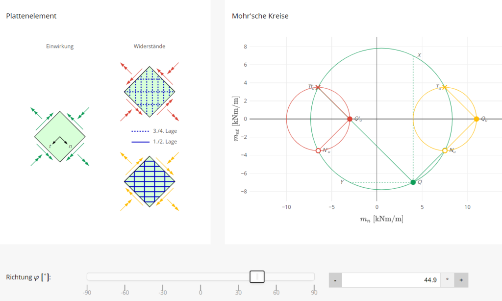
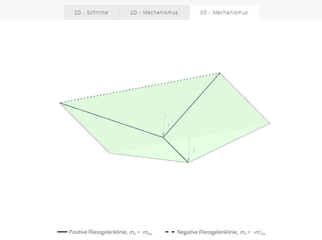
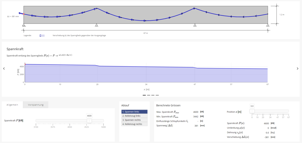
The digital apps have also been supplemented with some physical models. For example, we use a pre-stressed beam that consists of foam segments. The phenomenon of pre-stressing and decompression of the cross-sections can be shown in either the physical model or the simulation. We would also like to compare actual tests from our experimental research with the simulations in the future. After all, even these virtual experiments – albeit dynamic and animated – remain an analytical model. Only the observation of actually loaded elements and structures may create a better understanding of the real-life behaviour compared to the analytically derived failure states.
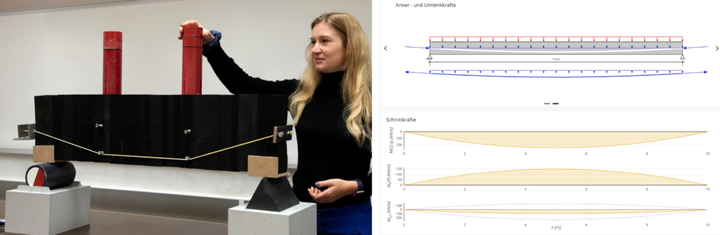
Challenges in development and implementation
The development of the web applications and their implementation in the existing curriculum presented a great challenge. Our everyday life is already strongly influenced by digital apps of various kinds, and especially the digital native generation has high demands on user experience. In addition to the engineering competence, the design of the applications and the web platform was one of the governing success factors. The apps should have a recognisable appearance and should be intuitive in use. The platform should also allow easy access so that the future generation of assistants can continuously develop the applications. Therefore, working out the technical basics took some time, and several iterations were necessary before we could even program the first app.
We wanted the web applications to be perceived as an integral part of the teaching. We could not simply introduce them as an additional element in an already highly dense course. According to a student survey, the applications were much appreciated as a presentation tool during lectures, and they were also actively used in exam preparation. However, there seemed to be little engagement with them during the semester due to a lack of time. This encouraged us to push for further adaptations in the colloquia and exercises to promote the applications in “everyday” use.
Conclusion and further future possibilities
The development and introduction of digital learning applications opened up broader possibilities for us to develop our teaching content in lectures and exercises, where we especially see advantages in the dynamic visual interaction with the students. This is only a first step in the digitalisation of teaching content. There are already many more ideas for new innovative teaching methods, such as augmented reality (mixing real environment with digital content) in bridge design.
However, we are still convinced that the foundation of our teaching approach in structural concrete is based on the rigorous application of equilibrium and mechanically consistent models. For this, we still see paper and pencil as the best tools. Nevertheless, we would like to invite you to explore the applications yourself. There is always something new to discover even in “Structural Concrete 101” – be it during studies, in practice or in research.
Acknowledgements
This teaching project was supported by the Innovedum Fund of ETH Zurich. Many thanks go to all those involved in the development and implementation of the applications.
Project lead: Prof. Dr. Walter Kaufmann, Minu Lee
Web design and development: Sebastian Wehrli
Applications: Lukas Gebhard, Nicola Gehri, Nathalie Reckinger
Revision: Fabian Morger, Andreas Näsbom
Links
Collection of all digital applications for structural concrete:
https://concrete.ethz.ch/applikationen/
Learning and Teaching Fair:
https://learning-teaching-fair.ethz.ch/project/visual-interactive-learning-applications/?view=grid
Innovedum project database:
https://ethz.ch/en/die-eth-zuerich/lehre/innovedum/projektdatenbank.html
Minu Lee
Link zur deutschen Version: Lokale Korrosion der Bewehrung – kleiner Schaden mit grosser Tragweite
The reinforcement of many ageing reinforced concrete structures is corroding. The reasons for this are manifold and range from the carbonation of the concrete and the ingress of chlorides to a concrete cover with high permeability. There is a considerable damage potential, especially in the case of pitting corrosion, due to the very high corrosion rate as a consequence of macro-element formation (the cross-section loss is typically in the range of 1 mm per year). But what are the effects of localised corrosion on the load-bearing and deformation capacity of affected structures? That is what this blog post is about.
Hidden damage – huge uncertainty
A pilot study conducted by the Federal Roads Office (FEDRO) revealed that many cantilever retaining walls along the motorways built in the 1960s and 1970s are corroding. On average, about 36% of the examined reinforcing bars showed corrosion damage, and the mean cross-section loss of the affected bars was 25%. Affected is the flexural reinforcement on the side facing the ground above the construction joint between footing and wall. The local corrosion is highly probable to be caused by honeycombs, i.e. a highly permeable concrete cover, resulting from improper casting and compaction of the concrete, without any chloride ingress.
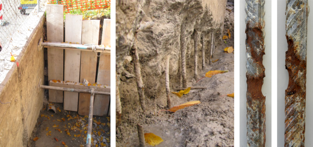
In the pilot study, corrosion detection proved to be extremely difficult for such structures. The thickness of the walls above the footing impeded any reliable statement on the reinforcement’s condition at the opposite side using standard measuring techniques. Only visual inspection revealed the extent of corrosion damage, which required building shafts behind the wall and removing the (damaged) concrete cover.
The uncertainty regarding the number of affected structures and their load-bearing behaviour impelled FEDRO to launch five research projects together with the Federal Office of Transport (FOT; the railways also have many retaining walls). We are pleased to work on one of them. The project investigates the load-bearing behaviour and deformation capacity of cantilever retaining walls with locally corroding reinforcement. An initial analysis at the beginning of the project indicated that the load-bearing capacity of these structures is likely to be disproportionately reduced (i.e. the residual capacity would be overestimated if only the loss of cross-section was considered). In addition, the deformation capacity is drastically reduced due to the localised damage. The latter is particularly relevant as these walls were initially designed to resist active earth pressures, which was in accordance with the code provisions at that time. This approach presumes a deflection of the wall and therefore a sufficient deformation capacity at the ultimate limit state. If the deformation capacity is reduced, an increased earth pressure action has to be considered (in extreme cases even earth pressure at rest) in addition to the reduced load-bearing capacity. This combination is an uncomfortable starting point for any assessment.
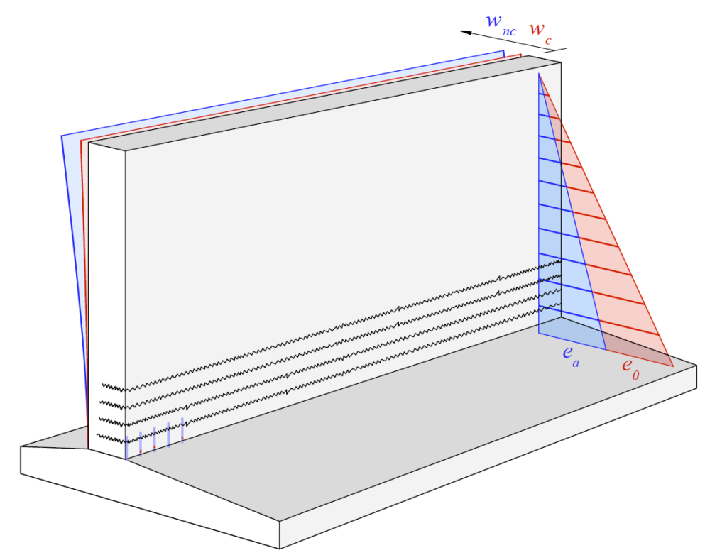
Local corrosion – diverse effects
It is widely recognised among the research community that the damage geometry (i.e. pit morphology) decisively influences a reinforcing bar’s behaviour in the vicinity of the pit. Due to the cross-section reduction, stress trajectories converge and an inhomogeneous, three-dimensional stress state occurs over the cross-section. The constitutive relationships, determined from tension tests on the undamaged reinforcing bar, are no longer valid.
Additionally, local bending moments occur due to a shift of the neutral axis in case of unilateral corrosion damage. Unilateral damage is often observed for pitting corrosion and the corresponding bending moments have to be superimposed to the tensile force. Although bending moments decrease as soon as the reinforcing bar yields (and a local plastic hinge is formed), ultimate strains are reached much earlier due to the large curvature. This may lead to a premature failure, as experimental results of this project indicated.
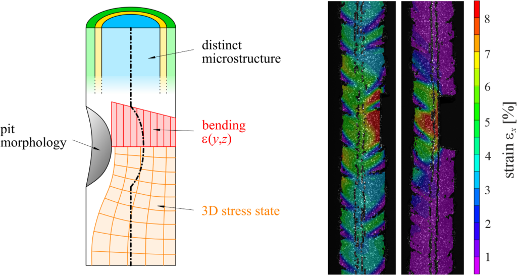
Since the late 1970s, the majority of reinforcing steel worldwide is produced using a process called “quenching and self-tempering” (QST, brand name “Tempcore”), so also in Europe. Due to this production process, these bars consist of three distinct material layers over their cross-section, which exhibit different material characteristics. Consequently, if a QST reinforcing bar corrodes, its mechanical characteristics are continuously altered with a progressing loss of cross-section. Especially, its tensile strength is reduced, as the innermost layer has an almost 30% lower tensile strength compared to the outer annulus.
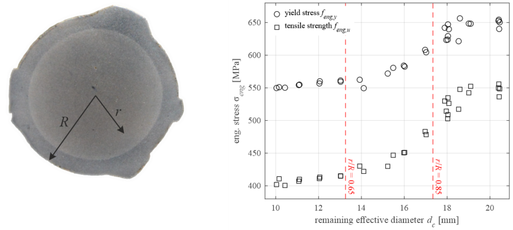
A short damage length proves to be highly unfavourable for a reinforcing bar’s deformation capacity. The bar deforms almost only in the damaged section, and strain localisation occurs. The critical point is reached if the ultimate force of the damaged section is not sufficient to yield the adjacent undamaged parts of the reinforcing bar. Thus, the bar almost lost its entire plastic deformation capacity. Considering today’s reinforcing bars produced in Europe, this is the case for comparably low cross-section losses between 12% and 20% (note that the mean cross-section loss reported in the pilot study of FEDRO was 25%). To make matters worse, the critical section for retaining walls lays just next to a lap splice (reinforcing bars are traditionally spliced above the construction joint), where a structure’s deformation capacity is reduced anyway, as a new yet unpublished study shows.
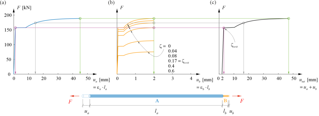
Example of a load-deformation curve of a reinforcing bar. Left: for the undamaged section A (blue); centre: for the damaged section B (orange); right: for the entire bar A+B. ζ = loss of cross-sectional area (between 0 (no loss) and 1 (bar is fully corroded)). The loss of deformation capacity is visible for a short damage length lb<<la and ζ between 0 (green) and 0.17 (pink).
Research on a small scale – and on a large scale
Besides more than 100 tensile tests on reinforcing bars containing various damage geometries, eight large-scale experiments on retaining wall sections were conducted in the Large Universal Shell Element Tester (LUSET) throughout this research project. The walls had a width of 2.0 m, a height of 1.7 m, and a thickness of 0.38 m. They were built on footings measuring 2.1 x 0.4 x 1.4 m. The elements weighed more than six tons and represented the lower part of a 4.7 m tall retaining wall. According to this height, the load was introduced at the element’s head in LUSET as a combination of normal force, shear force and bending moment.
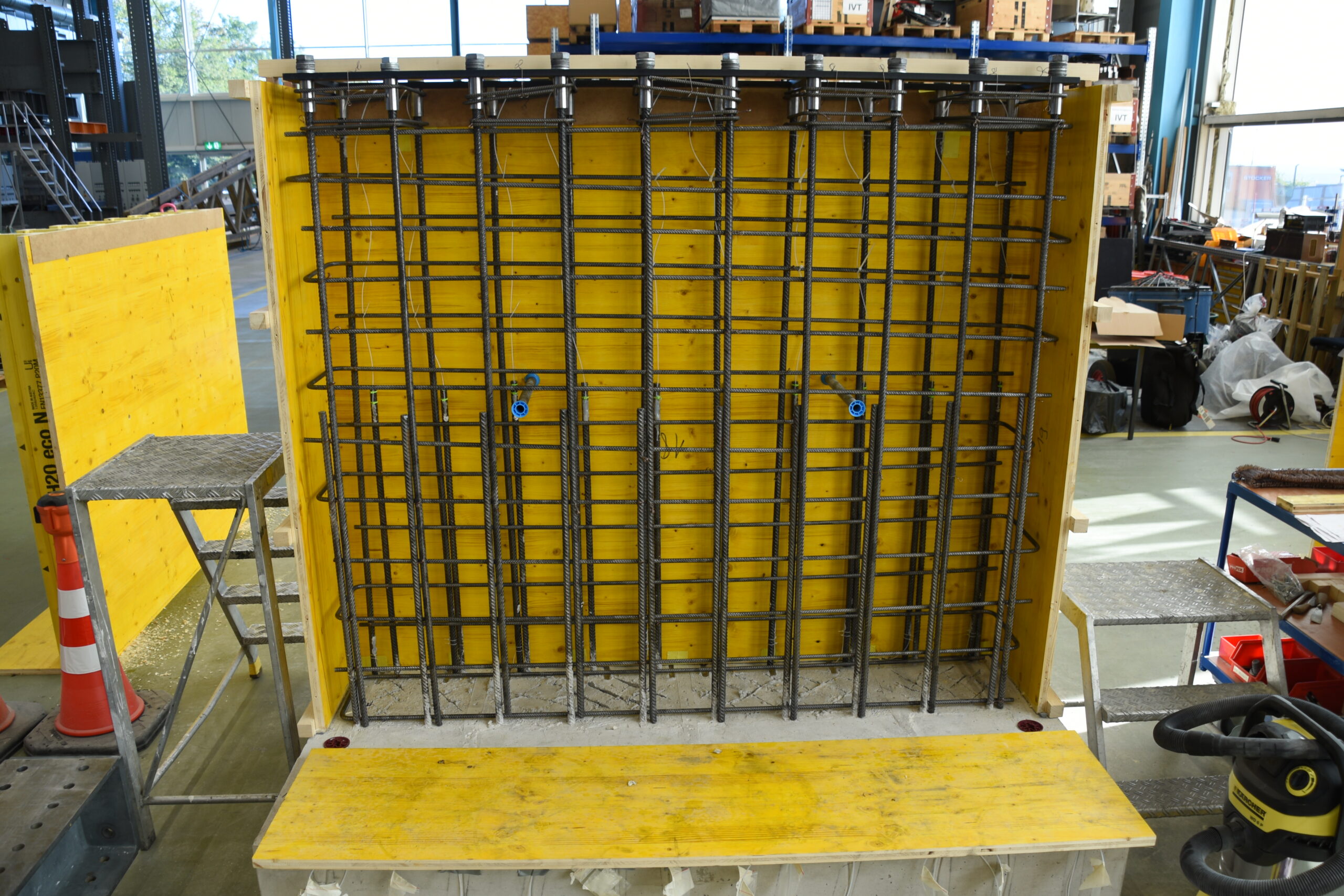
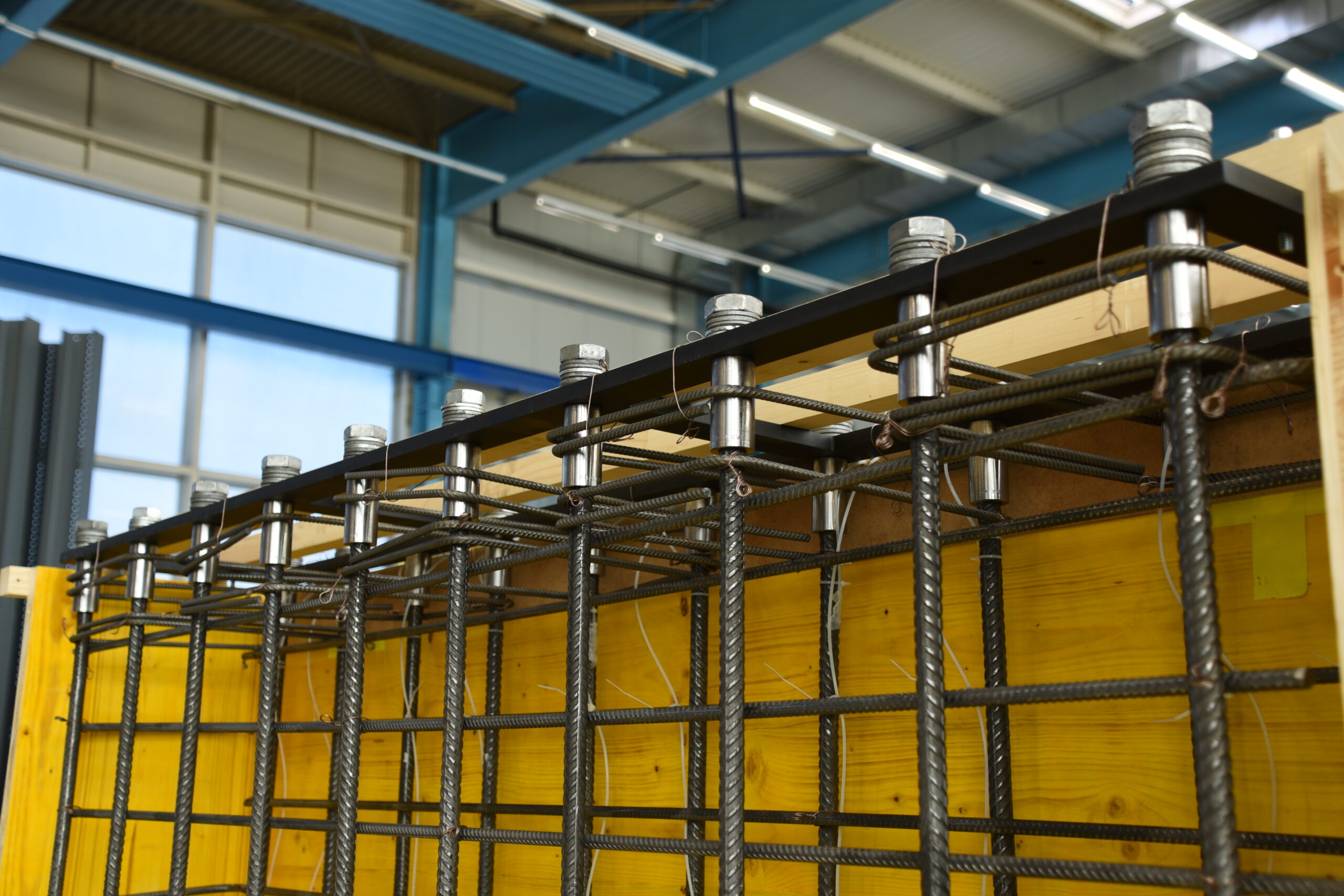

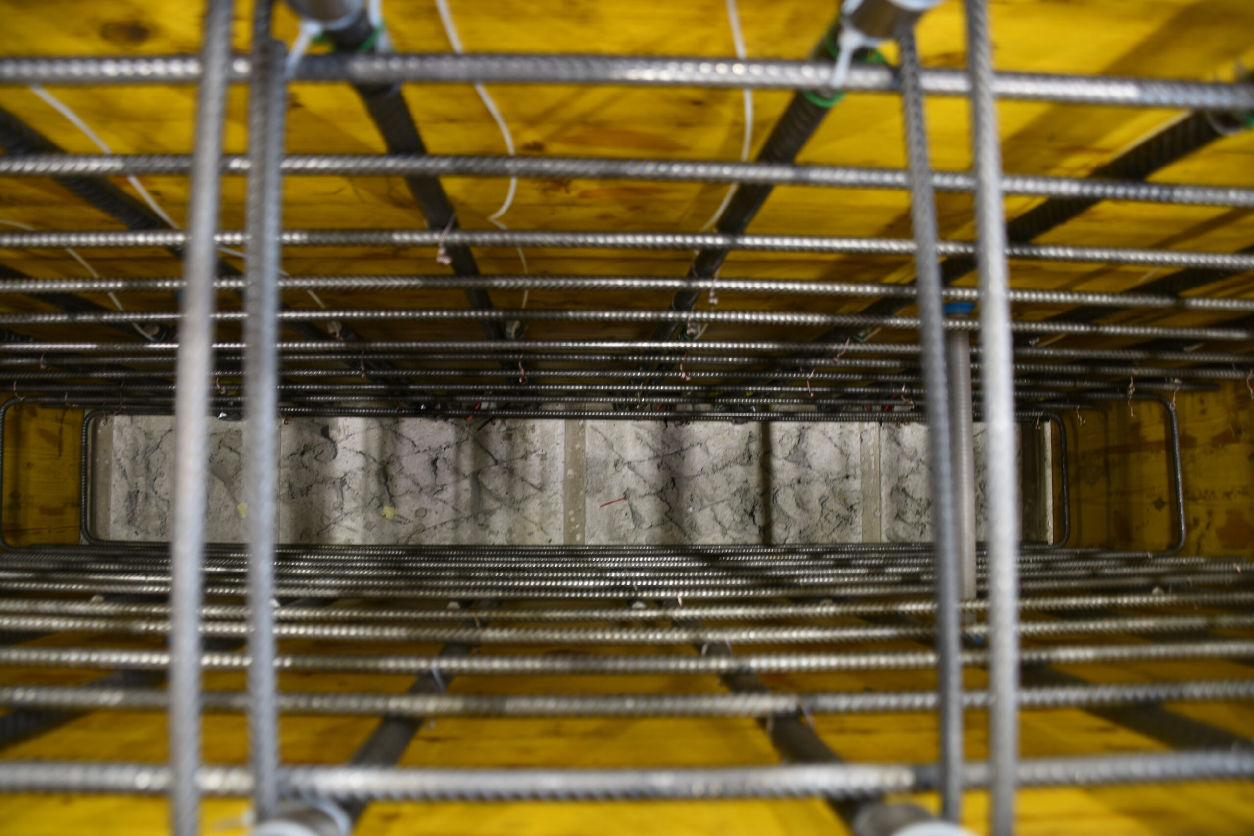
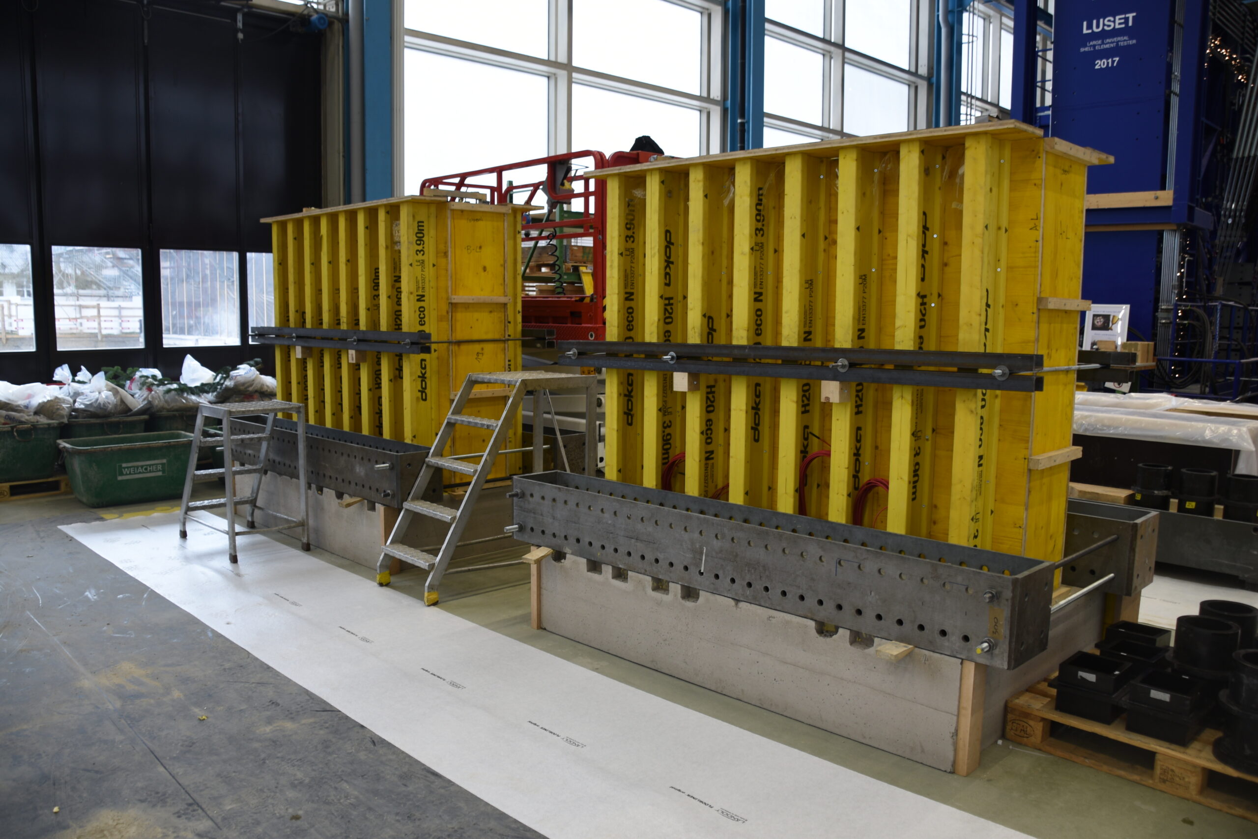
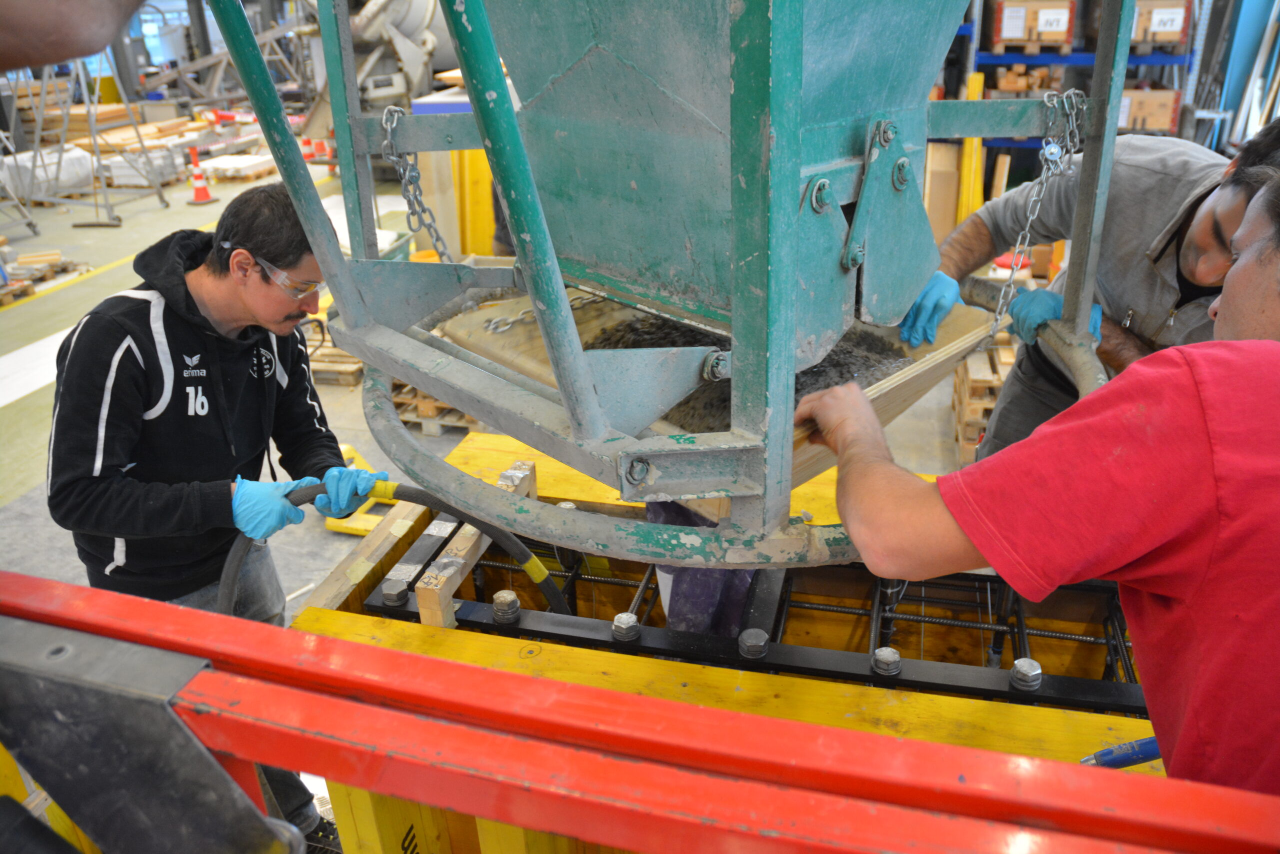
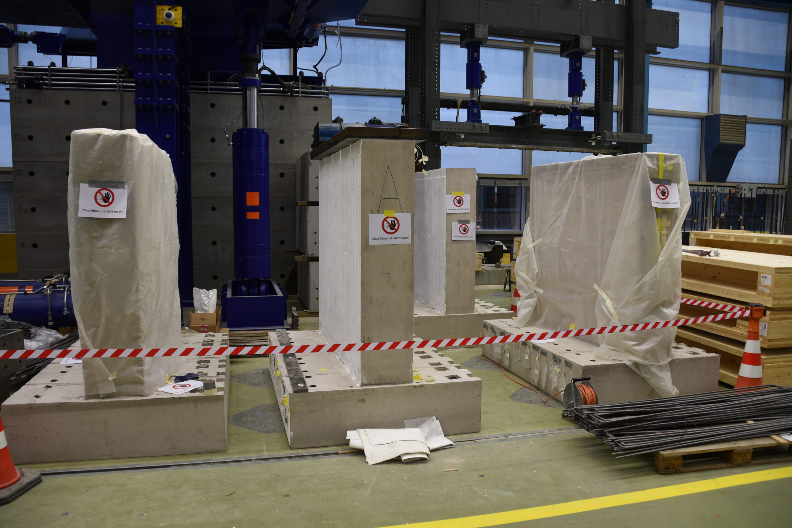
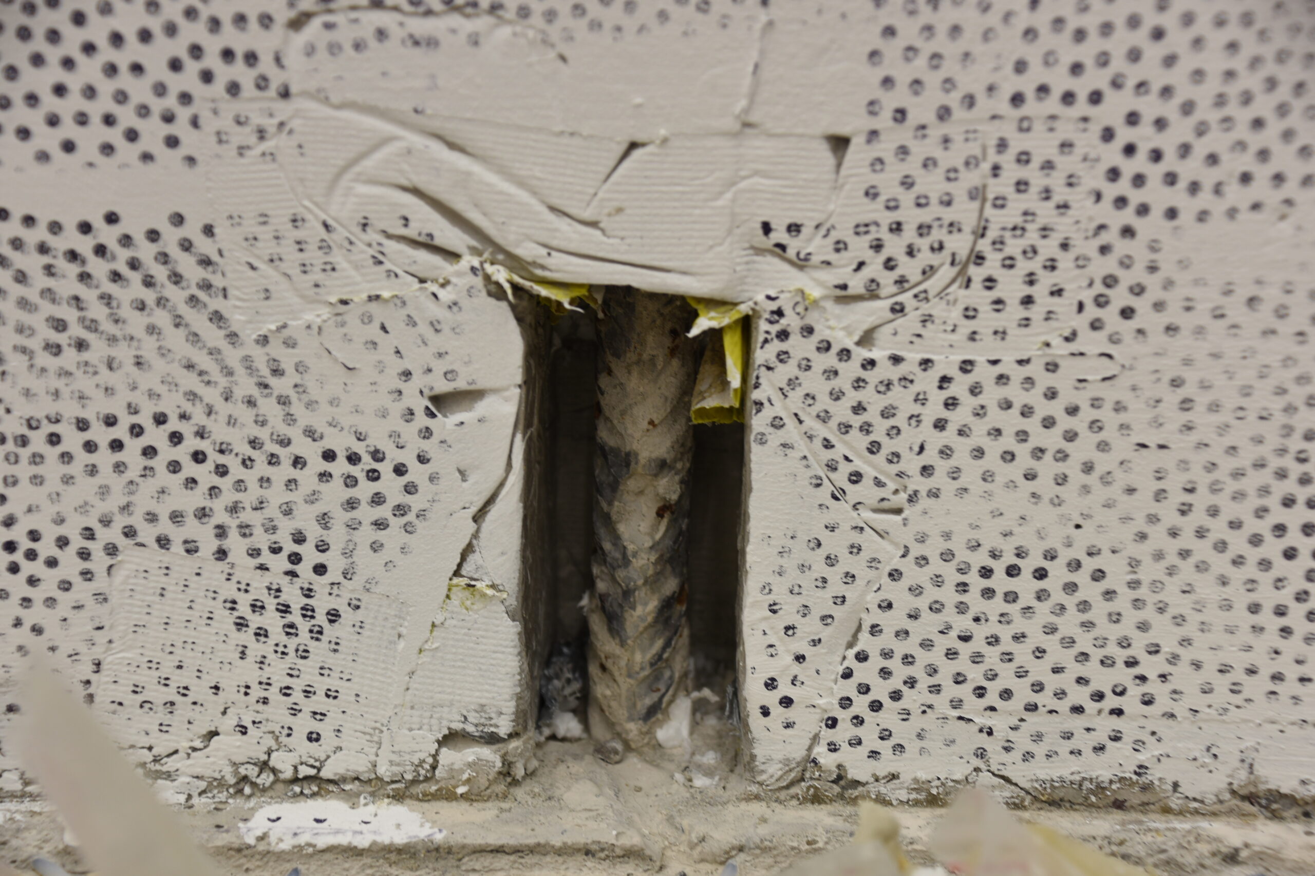
The specimens were instrumented using cutting-edge measurement technologies. Stresses in the reinforcing bars were calculated using fibre optic strain sensing with a few millimetres’ spatial resolution. The wall’s deformation and the kinematics of the formed cracks were measured with a three-dimensional digital image correlation system (DIC) with an accuracy in the range of hundredths of a millimetre.
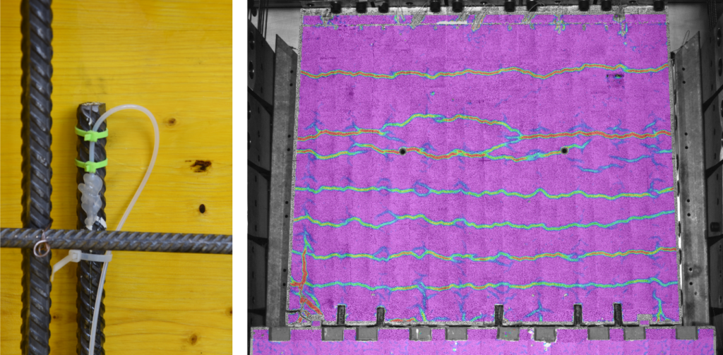
To investigate the influence of cross-section loss due to corrosion, some of the reinforcing bars were intentionally damaged prior to the experiments using a 20 mm diameter spherical mill. This type of “artificial corrosion” causes practically the same effects as “natural corrosion” induced electrochemically, as was shown by preliminary tests in collaboration with Prof. Dr. Ueli Angst. In three hybrid tests, four (of 10) reinforcing bars were damaged stepwise during the experiment using fully automatic drilling machines, which were installed at the footing of the wall. The applied load was continuously updated using the actual displacement of the wall’s head and a model provided by the Chair of Geomechanics (Prof. Dr. Alexander Puzrin, David Perozzi), which is capable of simulating the acting earth pressure as a function of the wall deflection. This ensured a realistic loading of the specimens.

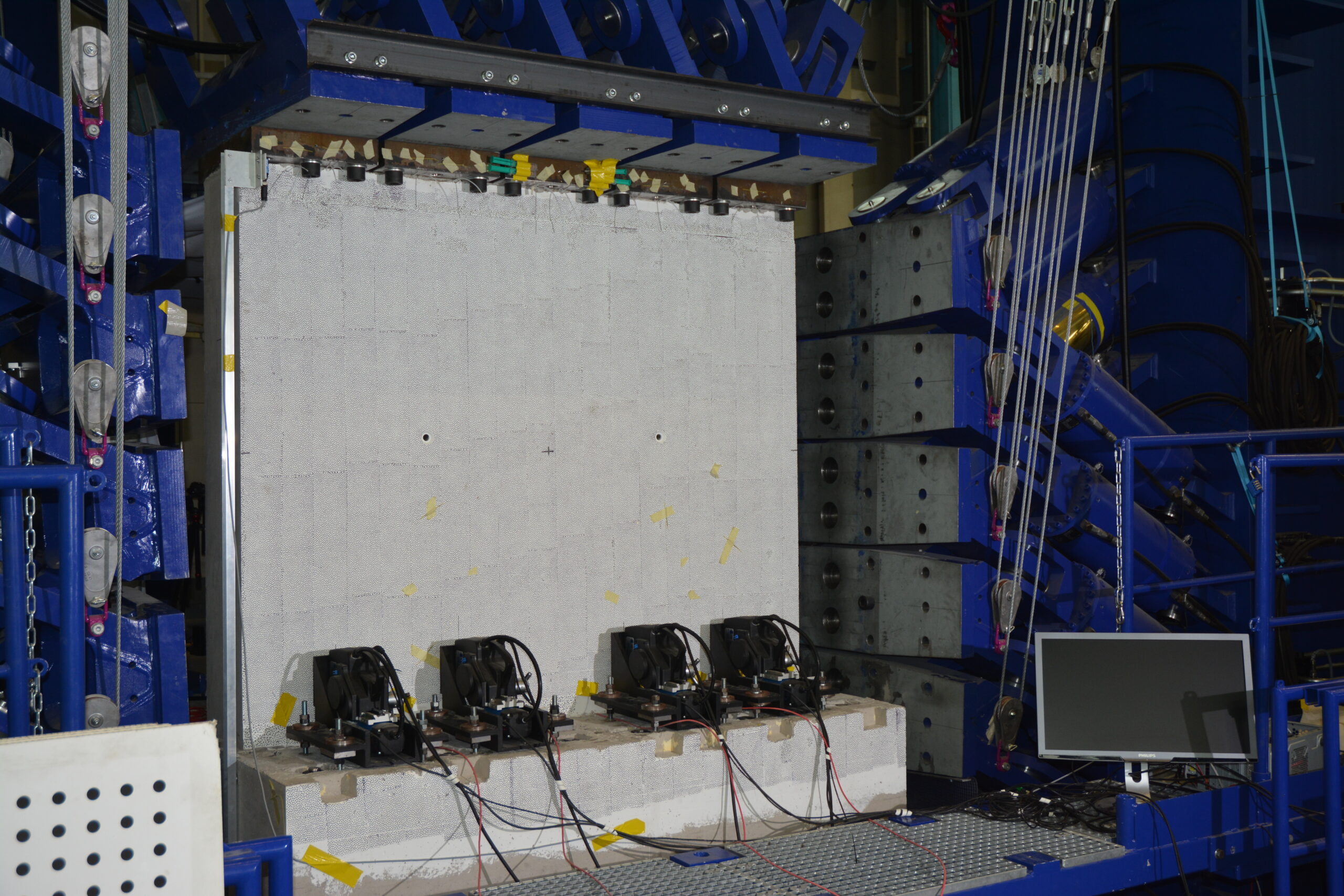

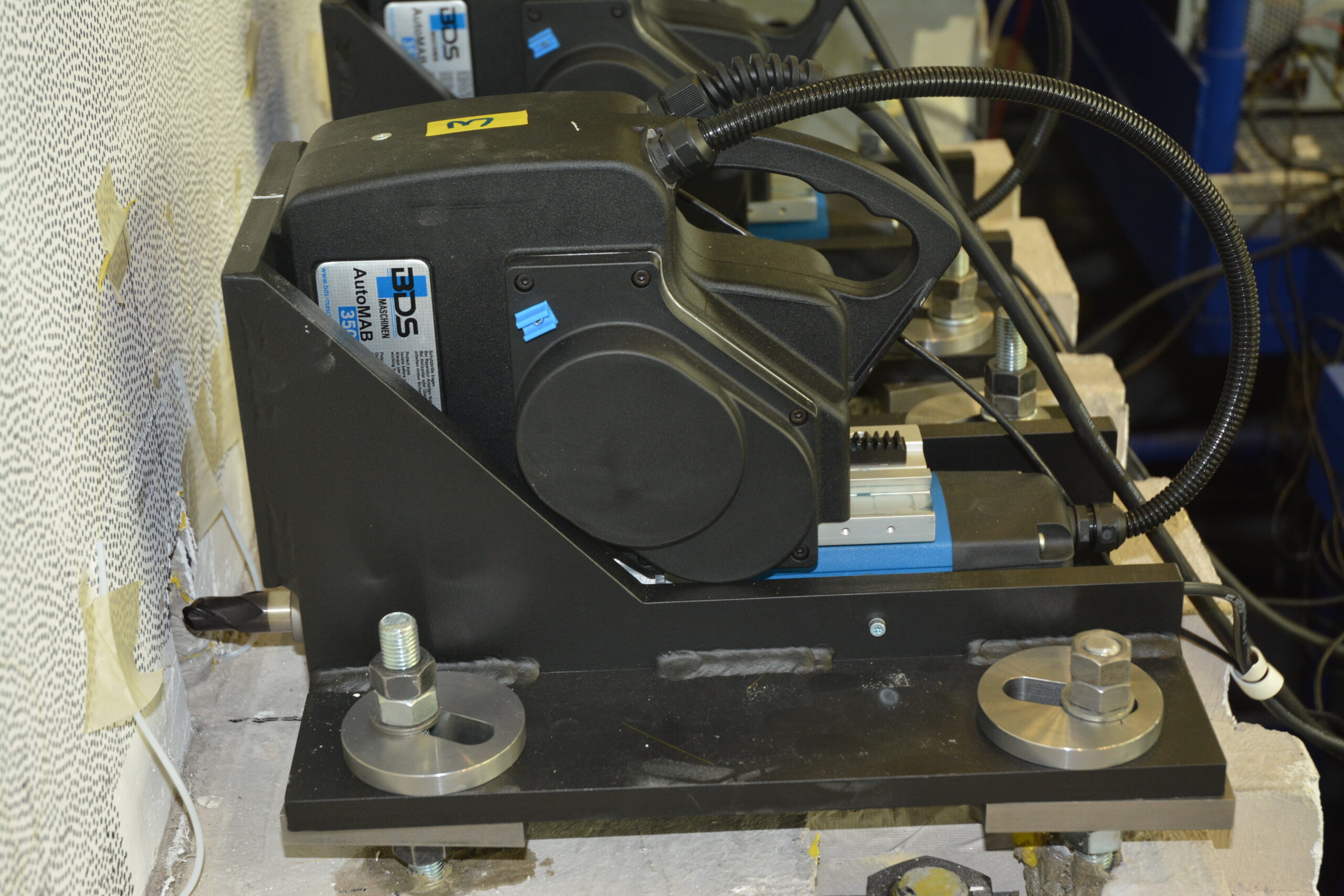
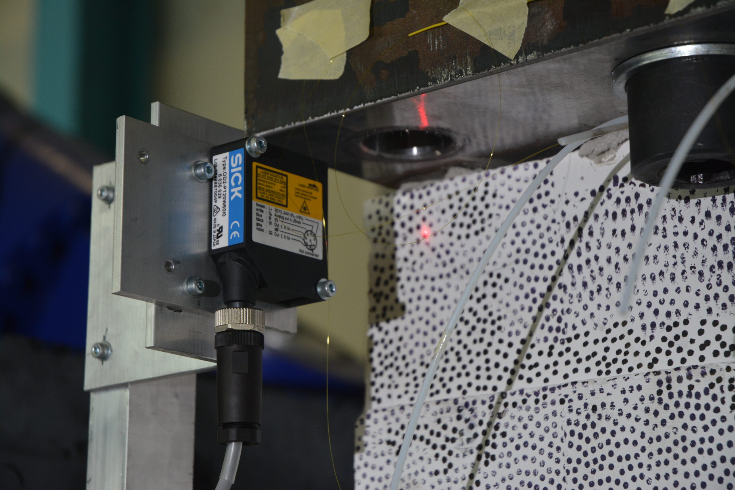

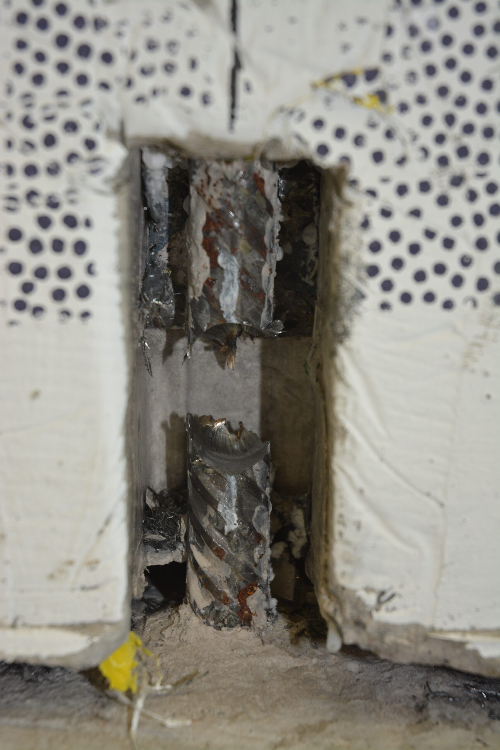
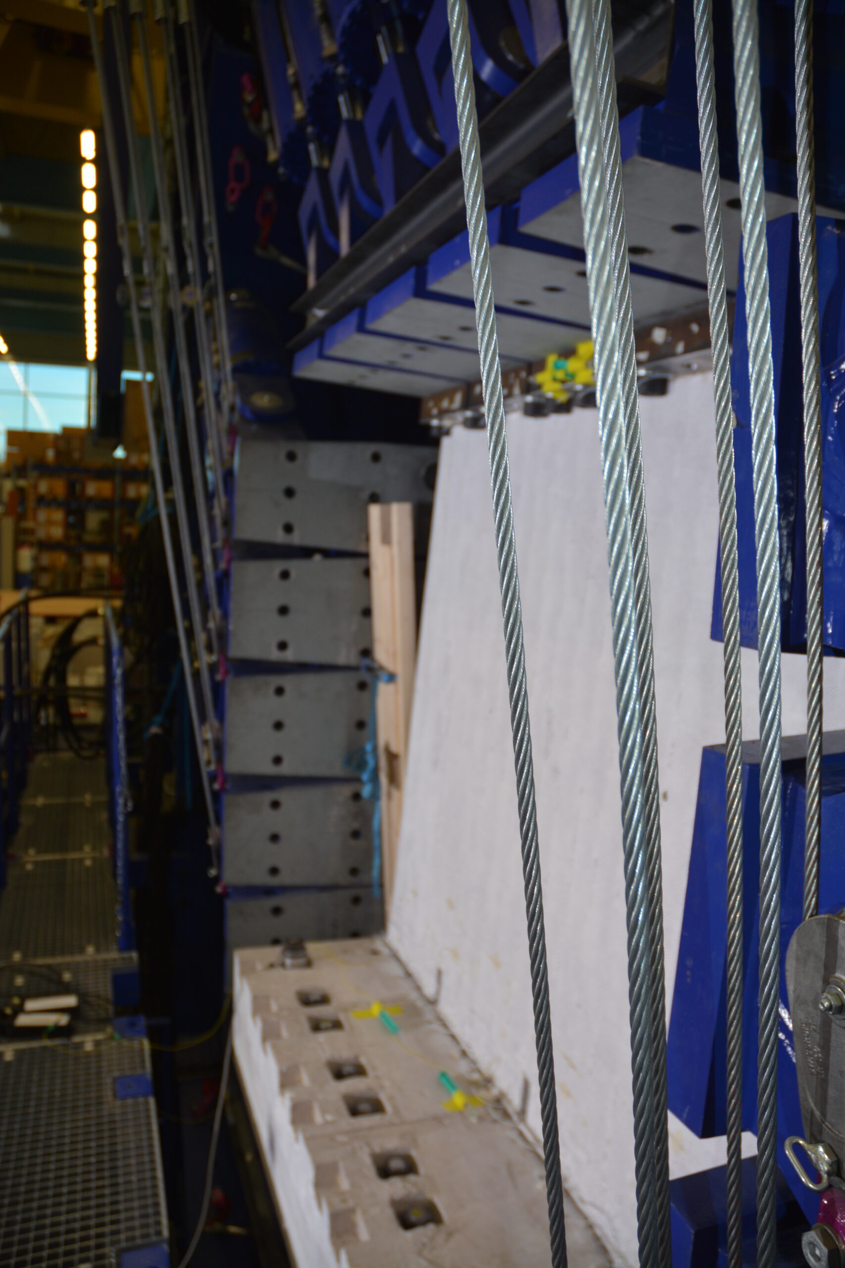
What was found out up to now – and what is still to be investigated in the future
The load-bearing capacity of structural elements affected by local reinforcement corrosion is reduced disproportionally due to local phenomena in the vicinity of the corrosion pit. Models only considering the loss of cross-sectional area therefore overestimate the actual residual load-bearing capacity.
Local damage of the reinforcing bars leads to a substantial reduction (up to 85%) of an element’s deformation capacity, even for low cross-section losses. Hence, all models based on the lower bound theorem of plasticity theory – which most models in the codes are – are no longer valid without restrictions. Therefore, the actual deformation capacity of a structure needs to be assessed in detail.
The results of the conducted experiments on reinforcing bars and retaining wall sections prove the statements made above convincingly. The models developed in this research project are based on an extension of the established Tension Chord Model and are very promising to describe the load-deformation behaviour of structural elements affected by local corrosion. They can be used to assess cantilever retaining walls and other structural elements, whose deformation capacity is decisive (e.g. section over interior supports for continuous bridge girders).
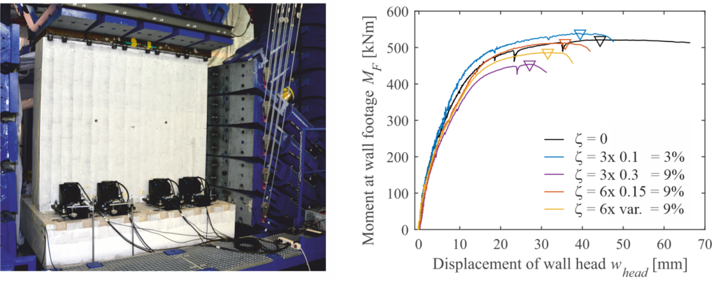
One of the aims of this project is to formulate a (simplified) assessment guideline for practitioners. It is still discussed how these research results can be used by engineers in charge of assessing structures with localised corrosion. The discussion focuses on the consequences of the challenging corrosion detection and if and how the observation method can be used to further operate corroding retaining walls safely.
Whether filigree retaining walls are “passé”, as it was the title of an interview in Tec21 (40/2016), is finally a decision of the owner of these structures. The exposure is generally moderate (in contact with the ground, semi-humid, without chlorides). Therefore, such structures are not more vulnerable for corrosion than other structures under the same conditions, provided the use of state-of-the-art construction methods (meaning the use of a so-called “kicker formwork”, thorough compaction of the concrete, and covering the construction joint if needed). However, a general change of paradigm to massive heavyweight retaining walls, accompanied by a comparatively high use of resources and greenhouse gas emissions, is not indicated from our point of view.
Severin Haefliger
Link zur deutschen Version: Schalungsloses Bauen von gekrümmten Betonwänden
Concrete is by far the most used building material today. Its ability to be moulded into any shape has certainly contributed to this success. From early on applications during the Roman Empire until today, fresh concrete has typically been cast into a formwork. Do you know about current research to avoid formwork when building concrete structures? In this post, I will introduce recent advances on digital fabrication processes with concrete, with a special focus on the formworkless Mesh Mould Prefabrication technology. These new digital technologies are opening the way to a more sustainable construction of optimised geometrically complex concrete structures, and could soon become standard on construction sites.
Limitations of conventional formworks for complex geometries
We have a wide range of industrial formwork systems on the market, which allow building concrete structures of simple or repetitive shapes very efficiently. The contribution of such formworks to the total environmental impact and cost of a structure is typically limited because they can be reused many times. This picture changes radically when building geometrically complex concrete structures. Such structures require very expensive, one-of-a kind formwork, which can often not be reused or even recycled.

Image credits: Fabian Scheurer, designtoproduction. 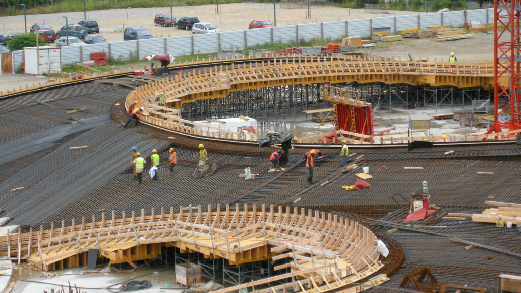
Image credits: INGPHI.
The pictures above show that building geometrically complex concrete structures with non-reusable formworks is far away of being economically and ecologically sustainable. In consequence, only unique projects can afford complex geometries such as double-curved surfaces today. Many of you might think that such structures are just a niche driven by aesthetical reasons. What is therefore our interest in finding ways to build them more efficiently? We have abandoned very efficient structural systems used in the past for the sake of construction efficiency. Our ultimate motivation is making the fabrication of materially optimised concrete structures affordable and sustainable, not just enabling extravagant designs.
How digital fabrication technologies might change the way we cast concrete
The increasing digitalisation of construction brings about many possibilities to tackle the challenge of building concrete structures with increasingly complex geometry at the same cost and even with lower construction waste. This research field is known as Digital Fabrication with Concrete. It covers a wide range of topics, from robotically fabricated reinforcement and additive manufacturing of concrete to computational design tools suitable for complex geometries. Our group is very active in this field, thanks to our involvement in the Swiss National Centre of Competence in Research (NCCR) Digital Fabrication. In another post, I will introduce the wide range of digital fabrication technologies that can be used to produce concrete structures. These technologies are either formworkless or use non-standards formworks. You may have heard about concrete extrusion 3D printing, which is by far the most widely researched digital fabrication technology. In this technology, a concrete element is produced without a formwork by extruding consecutive layers of concrete on top of each other.
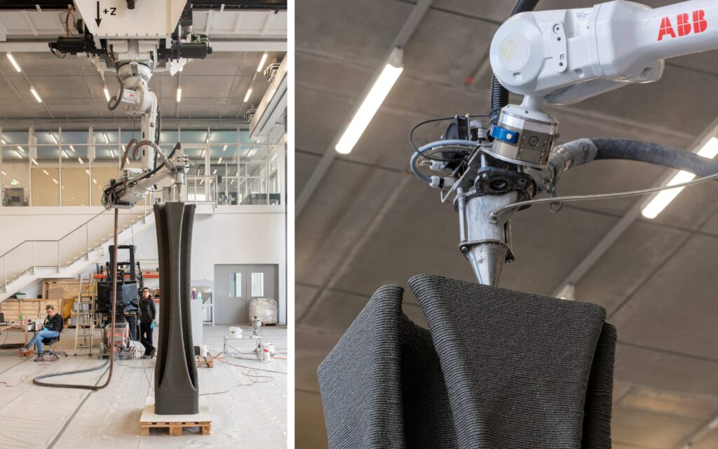
Thanks to great development in material science and technology, concrete 3D printing has reached a high degree of automation. However, building concrete structures with concrete 3D printing is still a challenge because there are no suitable strategies to integrate reinforcement, mainly perpendicularly to the printing direction. The high-tech 3D-printed walls built so far are typically unreinforced and have very low structural demands (typically single story buildings, as seen in the pictures below). They could have been built in masonry with a much lower cost and environmental impact.
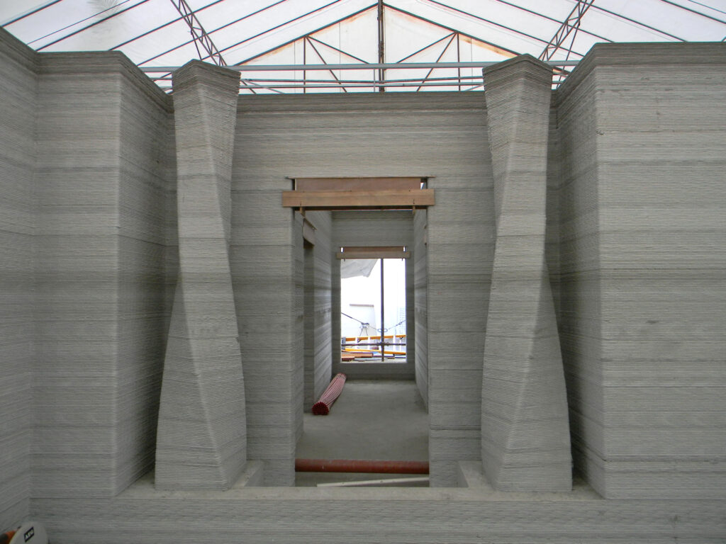
Suite in Lewis Grand (Baradi 2016). 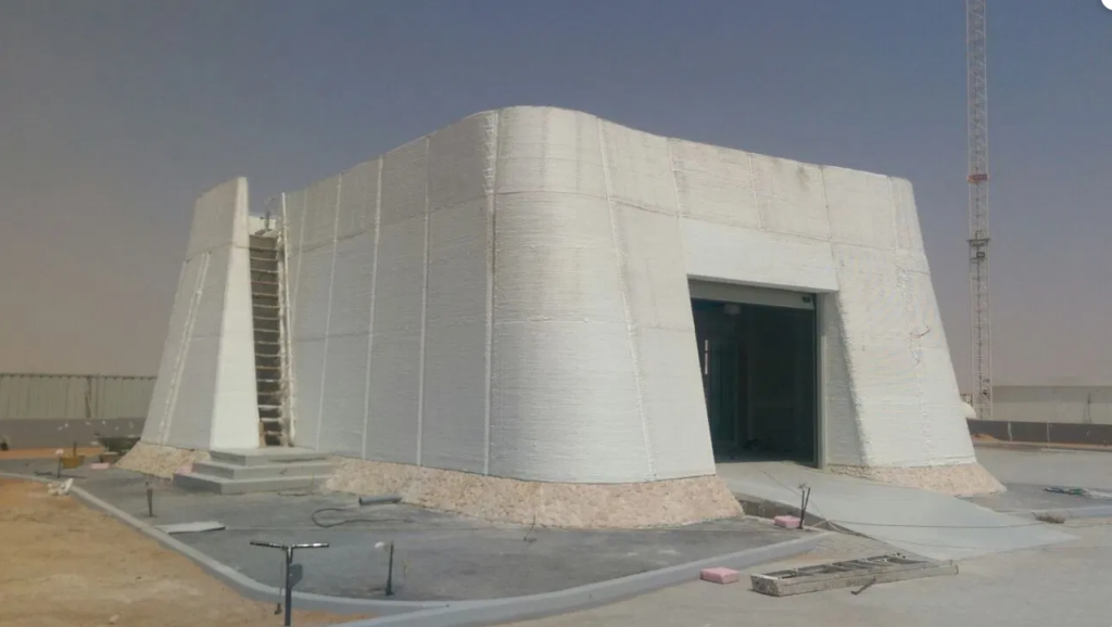
R&Drone Laboratory in Dubai (Cybe 2017). 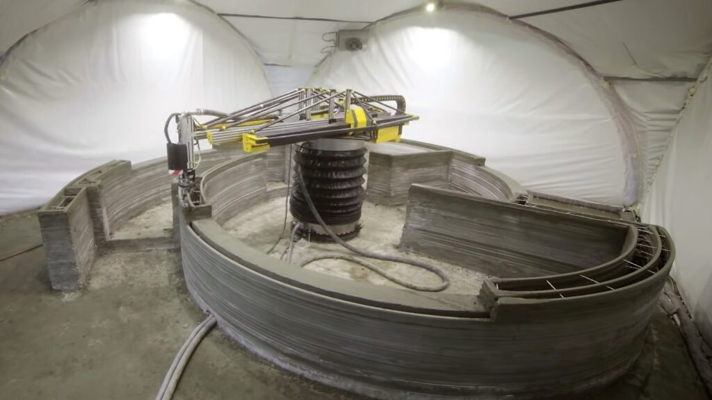
Apis Cor House in Russia (Skin 2017). 
Apis Cor House in Russia (Skin 2017). 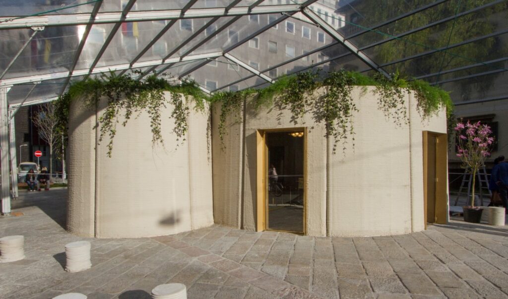
3D HOUSING 05 in Milan (CLS 2018). 
The BOD in Copenhagen (COBOD 2018).

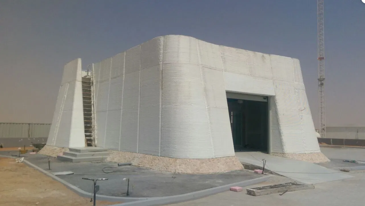

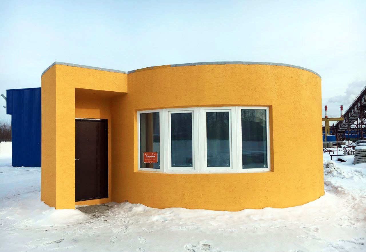

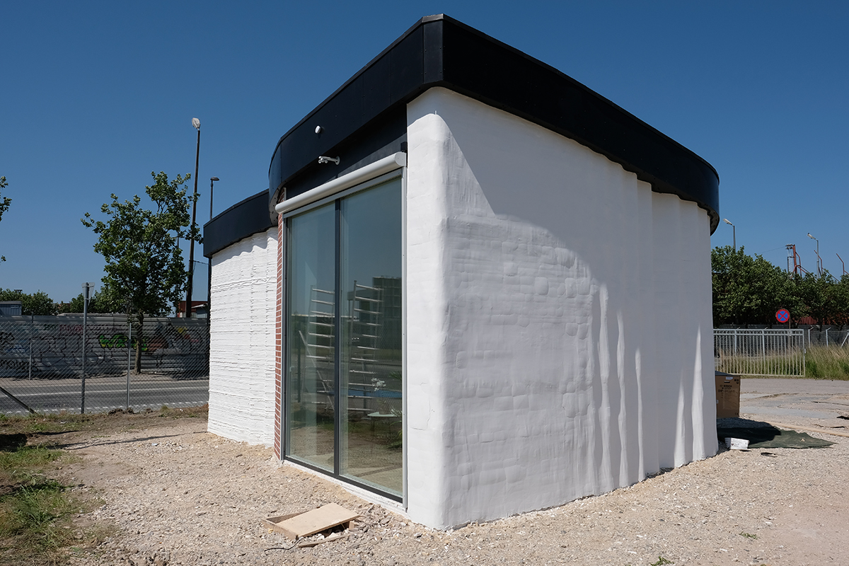
Mesh Mould: early research
Mesh Mould is another digital fabrication process that solves the difficulties to integrate reinforcement inherent to other technologies such as 3D concrete printing and allows producing efficiently double-curved load-bearing walls. Gramazio Kohler Research at ETH Zurich came up with the Mesh Mould concept already one decade ago, by revisiting the ferrocement system patented by Pier Luigi Nervi in 1943 with innovative digital processes.
The formwork which represents the real weakness of reinforced concrete from a constructive and economic viewpoint becomes absolutely superfluous with ferrocement. The metal reinforcement made up of netting and bars can adapt with great ease to curved surfaces or any type of skewing. Its intrinsic lightness and deformability mean that it can be supported with light scaffolding, which enormously simplifies the construction of large and very large roofs
P. L. Nervi: “Scienza O Arte Del Costruire?: Caratteristiche E Possibilità Del Cemento Armato”, 1945
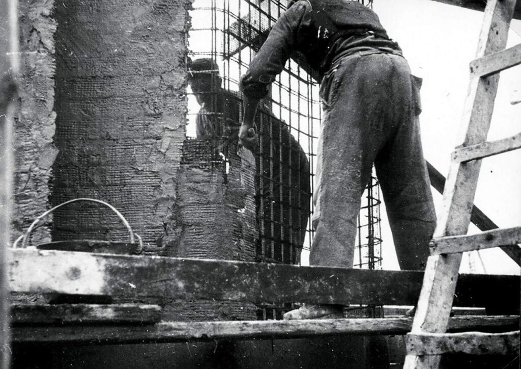
Manual application of cement mortar. 
Finished building, Rome, 1945. 
Exhibition hall, Turin, 1948.
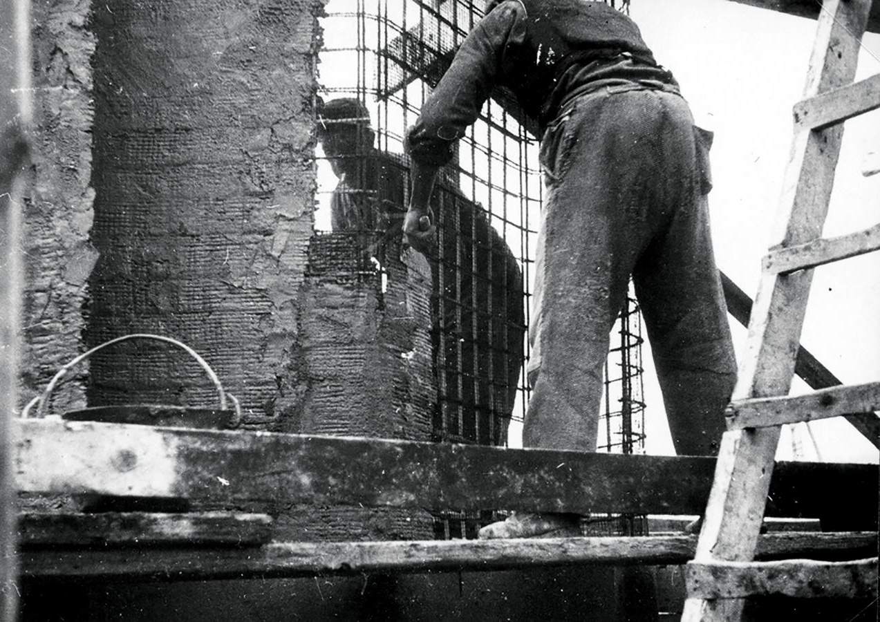
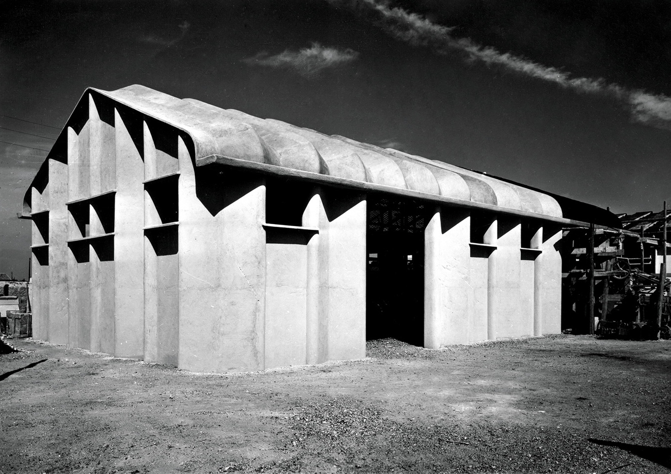
In Mesh Mould, a robot produces a dense reinforcement mesh. The mesh is filled with a special concrete mix that achieves sufficient compaction without flowing out the mesh.
Finally, the concrete cover is sprayed with shotcrete. While we often refer to Mesh Mould as a formworkless technology, strictly speaking, the reinforcement also serves as a stay-in-place permeable formwork. The geometric freedom of the walls produced with this technology is only constrained by the possibilities of the robotic fabrication of meshes. The great potential to build double-curved concrete structures efficiently, explains that we won the Swiss Technology Award 2016 in the category «Inventors» with Mesh Mould.
In the first phase of the project, the meshes were produced on-site by the “in-situ fabricator” robot. To test the possibilities and limitations of Mesh Mould in a real construction environment, we addressed the fabrication of a 12 m long and 120 mm thick double curved wall in the DFAB HOUSE, a residence opened in 2019 for research guests of EMPA at Dübendorf.
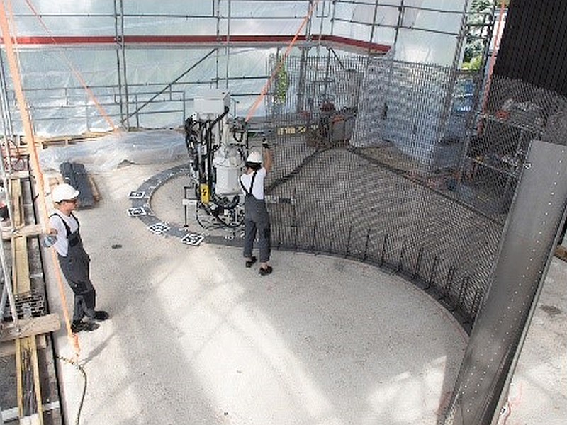
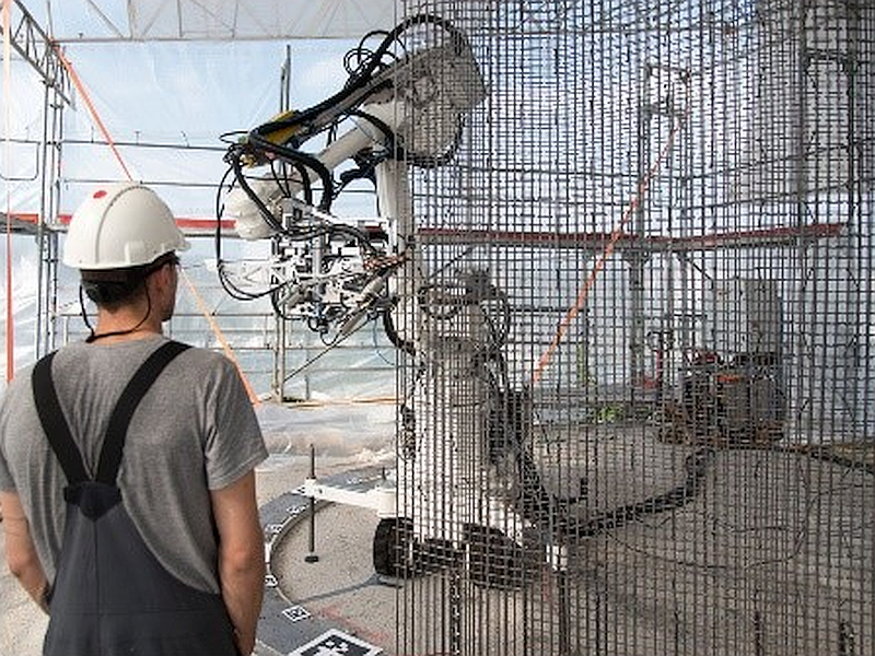
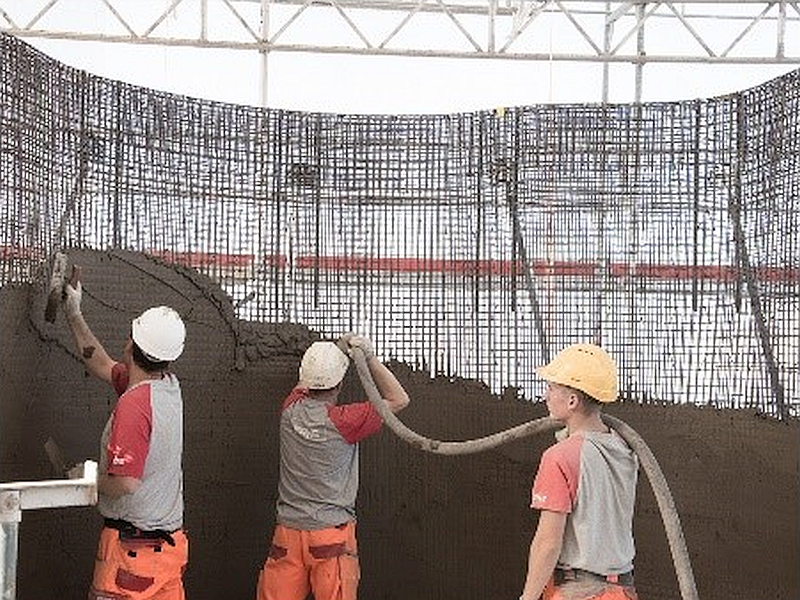
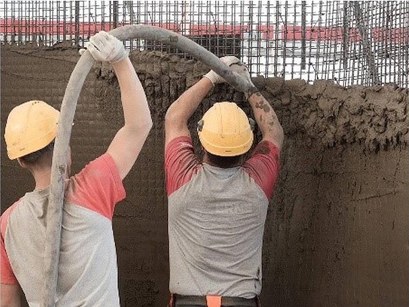


You can find more details of the production at the DFAB HOUSE in the video below. As you can see, the result is great but we identified several aspects to be improved during the industrial scale-up of Mesh Mould. On one hand, the casting was very labour intensive. From the structural side, the horizontal reinforcement was composed of small welded segments: a structurally inefficient solution driven by fabrication constraints.
Mesh Mould Prefabrication: industrial implementation
Thanks to the fruitful collaboration between our group, Gramazio Kohler Research and the industrial partners PERI and SIKA, we are further developing Mesh Mould to reach commercialisation. The meshes are now prefabricated in a controlled industrial environment to tackle the challenges faced in the DFAB HOUSE. Thanks to a novel, patented robotic wire application process, the reinforcement is now continuous in both directions. This automated bending and welding process enables the fabrication and layering of doubly curved meshes from steel rebar of up to 12 mm in diameter. The project includes the development of a competitive concrete mixture that ensures a robust onsite filling process providing good compaction.

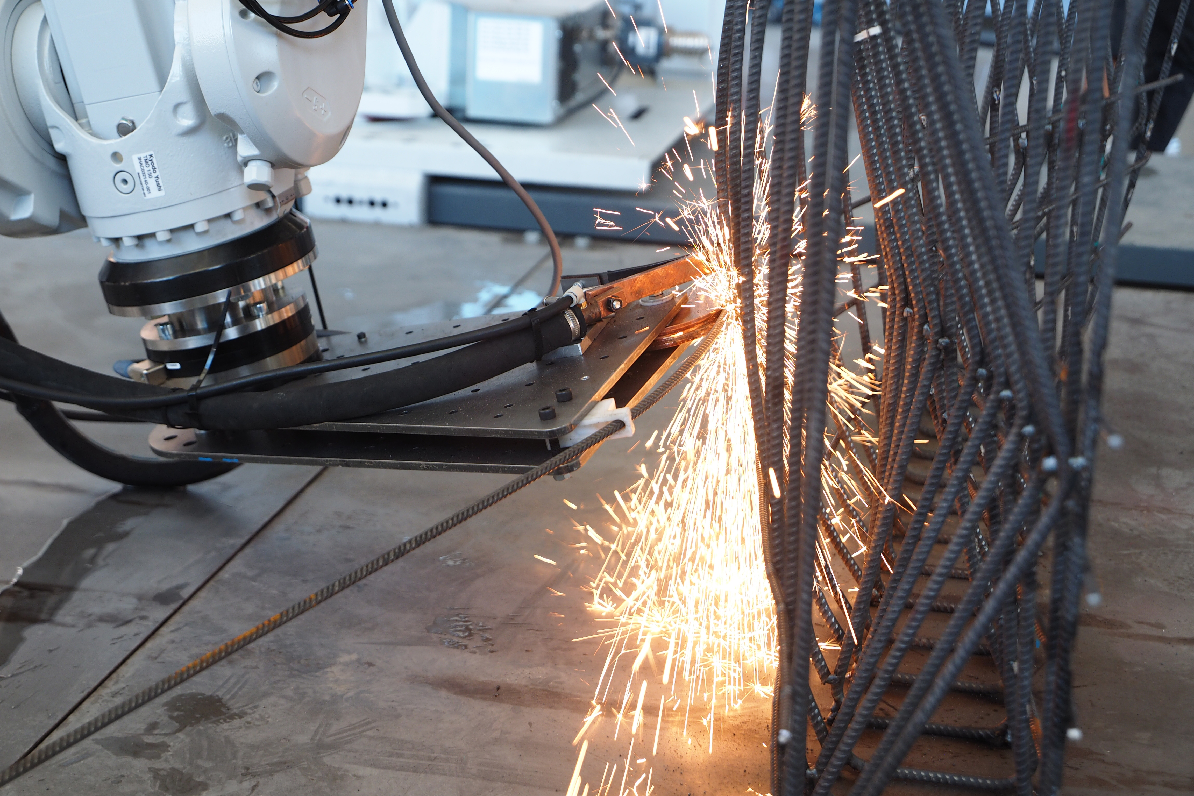


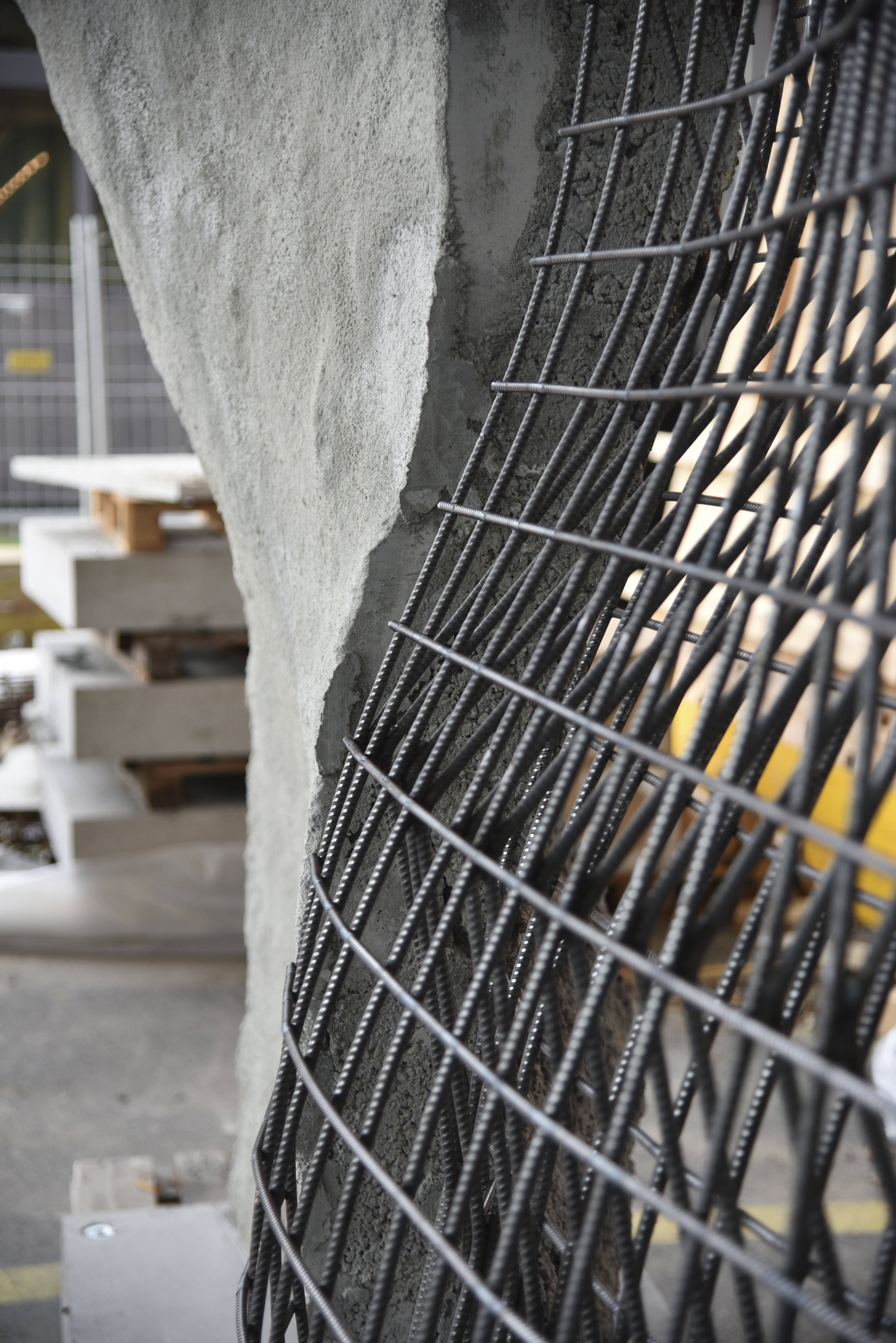
We are conducting an extensive experimental campaign to determine the structural behaviour of Mesh Mould Prefabrication. Thanks to the implementation of an innovative and automated structural design approach based on the sandwich model, complex Mesh Mould structures will not only be build but also dimensioned and optimised in a very efficient manner. We hope that this and similar efforts will soon make an impact towards a leaner construction of concrete structures.
Jaime Mata-Falcón
Link zur deutschen Version: Lehre während der Pandemie
Four weeks into the Spring Semester 2020, on March 16th, ETH Zurich suspended classroom teaching, and we have not returned to physical presence for more than a year by now. In this blog post, I would like to share my personal review of our teaching activities during this year, as well as some thoughts on potential long-term lessons from the pandemic.
Classroom teaching suspended
From today’s perspective, the decision of the Federal Council on March 13th to shut down all schools could have been expected. Still, it was surprising to many of us. Although our Executive Board had decided to suspend classroom teaching already the day before – we were informed by the Rector on March 12th 2020, 21:27 – we had to adjust our entire teaching practice over a weekend, including the procurement of webcams and microphones, identifying a suitable online teaching platform, finding alternative solutions for the blackboard, and much more. Thanks to the effort of everyone involved, we managed to master the related challenges and successfully taught our first online lecture on March 16th, using Zoom as our platform. Since then, we have taught all lectures and colloquia online at exactly the same time they would have taken place at in the classroom. We consider this the best way to support the students in keeping at least a part of their normal student life and daily routine.

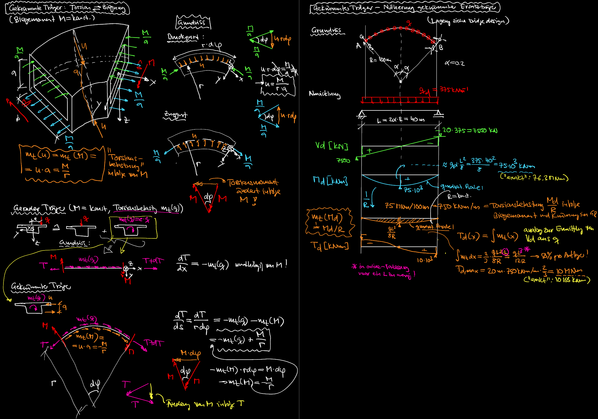
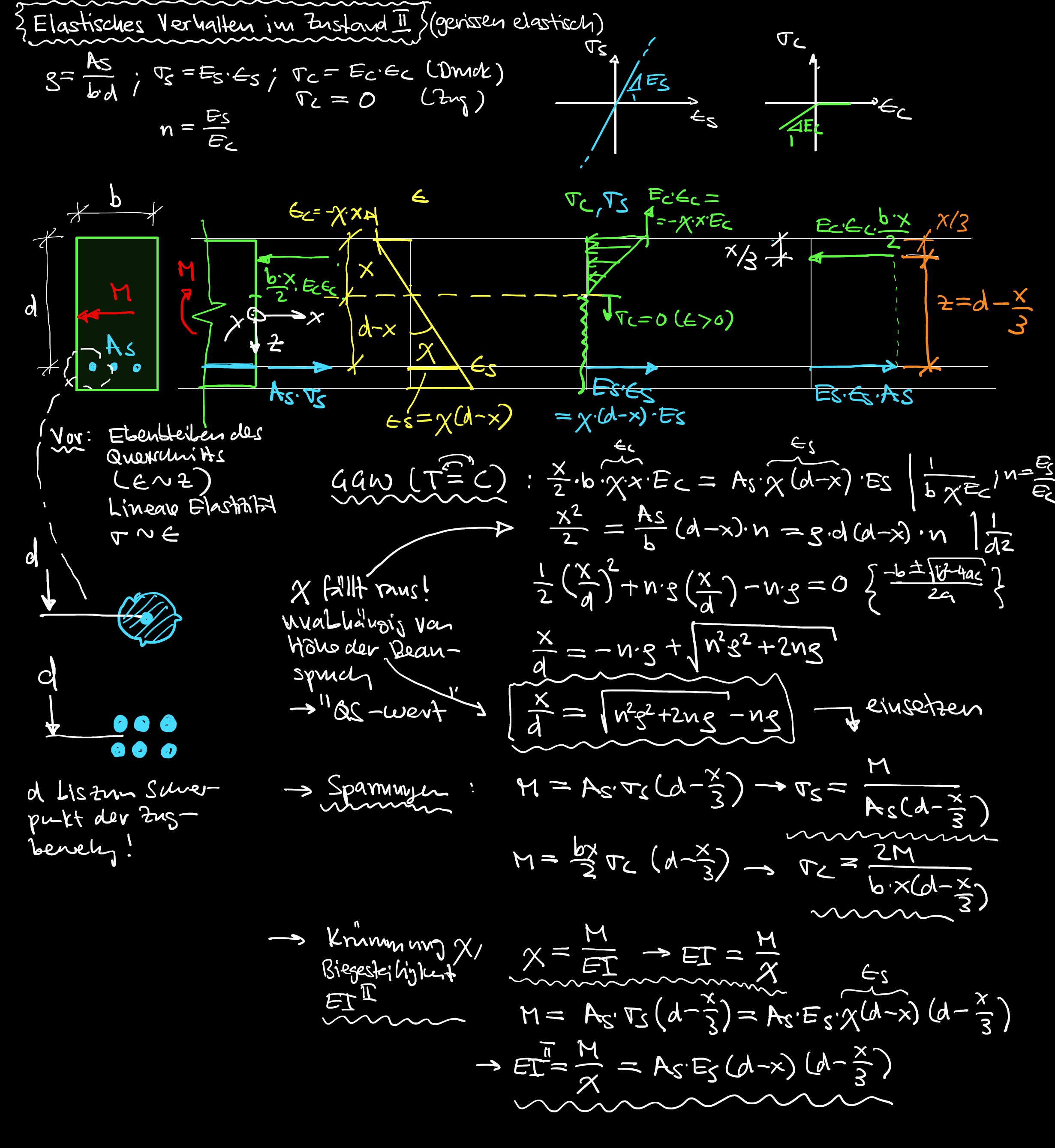
Lectures
For the lectures, we benefitted from our teaching platform concrete.ethz.ch that we had set up the year before: all course material was available to the students online already. Well, not really everything: The blackboard obviously could not be uploaded to the teaching platform, and finding an appropriate replacement for this didactic tool, which many students prefer to slides despite its old-fashioned appeal, was a major challenge. I initially used MS Whiteboard during the Spring Semester 2020, which made my writing look scribbly but otherwise gave decent results. However, the touchscreen of my Windows laptop regularly caused problems. Therefore, we switched to an iPad for the Fall Semester, when Dr. Jaime Mata Falcón is also teaching. While the writing experience of the iPad was clearly superior, its display was blurry when directly shared, and when connected via a Windows laptop, it frequently dropped the connection. Therefore, we are now sharing the iPad via a MacBook. On top of this, I am now also using our group’s teaching laptop, whose touch screen is superior to that of my personal device. This, in turn, allows me to connect my personal notebook as a participant to the lecture and check that it is streamed properly. With all these devices, my desk looks like that of a tech nerd reviewing devices for a laptop magazine during the lectures. And ironically, now that our streaming process has gone through this odyssey, the display quality of iPads shared directly in Zoom meetings recently improved drastically with a software update…
The course “Bridge Design”, which we were teaching in the Spring Semester 2020 for the first time, includes guest lectures by renowned bridge designers as well as flipped classroom exercises. Switching the guest lectures to the online format was a pity but worked well, and even the flipped classroom exercises could be carried out online successfully, by assigning the students to breakout rooms in a common meeting.
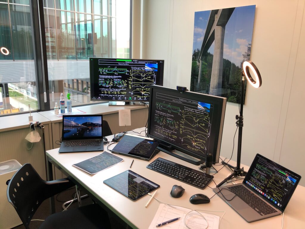
Colloquia
Apart from the lectures, the courses in Structural Concrete also include colloquia, which are taught by student assistants to smaller groups of students. Thanks to the skills and efforts of our student assistants, we also managed to seamlessly switch these to the online format during the Fall Semester 2020. An additional positive aspect are the web applications that we recently developed as part of our Innovedum grant: these can be used by the students on their own, but also in lectures and colloquia (more on these web applications and the entire Innovedum project follows in one of our next blogs).
Student projects
For the supervision of student projects, we essentially rely on the same online tools as for the lectures. During the first phase of the pandemic in March and April 2020, we were however facing a shutdown of the entire ETH, including offices and labs. This affected several experimental student projects, which we had to switch to theoretical theses. Thanks to the flexibility and effort of the students and their supervisors, all these projects could still be successfully completed. Since the Fall Semester 2020, experimental student projects have become possible again.
Exams
Fortunately, by the time of the regular exam sessions, the pandemic situation allowed to hold our written exams in physical presence. While this was also possible for the oral eams in summer 2020, we had to switch those to an online format in winter 2021. This was yet another challenge, since in our oral exams, the students sketch solutions to posed tasks on a whiteboard. Again, thanks to the effort and flexibility of all involved, this could be mastered surprisingly well. Overall, the performance of the students in the exams during the pandemic appeared to be slightly below previous years though, which may however be biased by the fact that the exams in summer 2020 did not count towards the maximum of 2 trials per exam. Perhaps a few students were tempted to take an exam less prepared than under normal conditions?
Conclusion
The transition from classroom to online teaching went very well, even much smoother than I had anticipated. This would have been impossible without the powerful online conferencing tools available today. As much as we may complain about software bugs: Can anyone imagine how ETH would have handled this pandemic had the virus decided to emerge 20 years earlier?
In fact, online lectures have their advantages. They can be watched at one’s own pace. Unclear or challenging parts can be replayed and boring ones skipped – I hope though that our students do not often need to use the latter functionality. Making recorded lectures available to the students is thus worth considering even after returning to classroom teaching. Furthermore, it is much easier to organise guest lectures by eminent speakers from abroad if they do not have to travel. Regarding the latter, the pandemic has also taught us that physical presence is not always necessary. I am convinced that after the pandemic we will travel less and thus be more efficient, while polluting less. However, online meetings cannot fully replace physical presence. This not only applies to activities such as excursions or experimental work, but equally to tasks that can actually be carried out remotely. For example, online project presentations cannot provide the students with the experience of physically presenting in front of an audience. Similarly, I deeply miss the feedback of the students in my online lectures – even if this used to be mostly nonverbal, apart from some questions during the breaks. And then, thinking back of my own student life, there is not much that I would prefer to have done “online”.
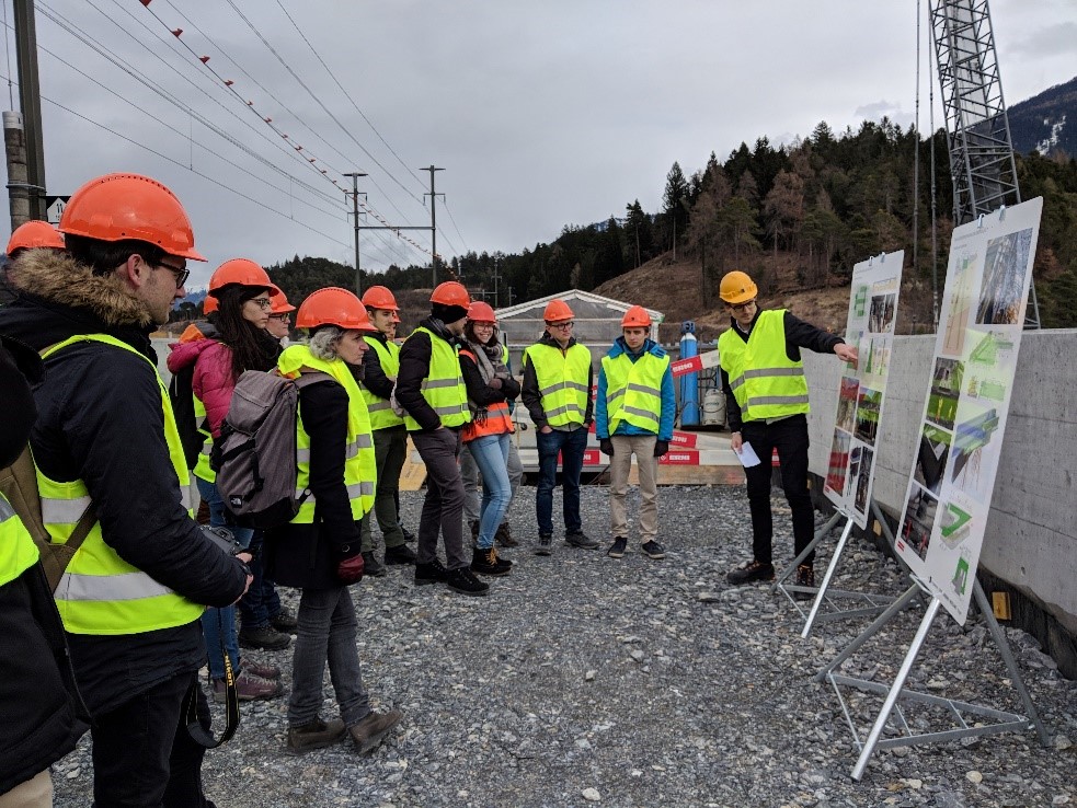
Today, it is not clear how long the pandemic will require us to keep teaching remotely. Just as a reminder, the master plan of our Executive Board dated April 15th 2020 envisaged a return to normal operations by the Fall Semester 2020 (which many found pessimistic). Still, I hope that we can return to classroom teaching no later than one year after that date, i.e., in the Fall Semester 2021. Whenever it will be, I am already looking forward to it.
Walter Kaufmann
The title of this blog entry is the most condensed possible description of what has kept me busy the past five years. Last December I successfully defended my thesis on this topic, which I completed under the supervision of Prof. Dr. W. Kaufmann. In this post, I will try to give you a slightly less condensed version of the thesis’ content, by providing answers to the questions that follow.
What is the problem and why is it relevant?
The reason for which in 2021 we are still discussing a load case for which code provisions exist, is linked to the fact that developed countries today are being faced with the challenge of ageing infrastructure. With traffic intensity as well as traffic loads having increased since their construction, many infrastructure objects need to be re-assessed in order to ensure their structural safety. Current design codes and guidelines are based on past research and associated models that were conceived with the purpose of safely designing new structures. They are therefore typically characterised by a certain degree of conservativism. While a certain degree of conservatism is certainly appropriate when designing new structures, as it comes along with an increase of robustness and redundancy at little extra cost, this does not apply to the safety of existing structures.
One of the load cases these structures have to be assessed for, as the title suggests, is the combination of in-plane shear and transverse bending. It is clear that loading a bridge box girder causes longitudinal bending and therefore longitudinal in-plane shear. At the same time, the loads applied to the deck also have to be transferred in the transverse direction causing bending in the section. As the web is monolithically connected to the deck it receives a large portion of the bending moment, which it is required to transfer in addition to the in-plane shear arising from the longitudinal load transfer.

What are the most widely used models and why was additional research required?
A group of approaches, which can be classified as rigid-ideally plastic models, make use of the observation that a potential bending about the vertical axis and or twisting deformation of the web element cannot occur as it is restrained by the deck, bottom flange and adjacent web elements, as well as by the presence of support and/or intermediate diaphragms. These deformations are therefore restrained and instead generalised reactions arise which take any value such as to ensure compatibility with these kinematic restraints.

The fact that the twisting moment can take arbitrary values, enables the lateral shift of the compression field, which is responsible for the transfer of in-plane shear towards the flexural compression side. This allows the stirrups on the flexural tension side to be utilised almost entirely for the transfer of bending moment, leading to considerably greater capacities.
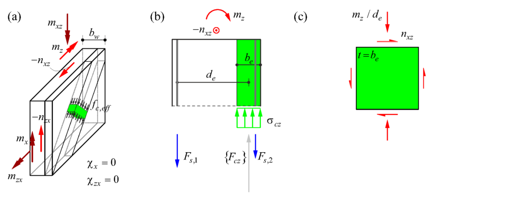
These rigid-ideally plastic models have the potential to provide good estimates of the web’s load bearing capacity. However, their applicability on members with very low stirrup reinforcement ratios is limited, since their fundamental assumption of sufficient deformation capacity cannot, in those cases, be deemed satisfied without an explicit verification.
Furthermore, these models have been validated on a very limited amount of experimental data. As a result, their second fundamental assumption of a lateral shift of the compression field, enabled by the kinematic restraints the web is subjected to, was never verified experimentally.
Another aspect that deserves attention is the fact that the transverse bending moments in the web are not known beforehand, but rather depend on the stiffness of the web relative to the deck. This effect has also not been investigated so far at all, neither theoretically nor experimentally. If the web exhibits sufficient deformation capacity, i.e. does not fail prematurely in a brittle manner but gradually loses its bending stiffness, transverse bending moments caused by eccentric traffic loads could be transferred from the web to the bridge deck, and transverse bending moments due to the distortion of the cross-section could be reduced as well (at the expense of an increase in warping torsion).
How were the knowledge gaps filled?
The knowledge gaps were filled by performing large-scale tests on panels that represented isolated web elements of a box-girder bridge in the Large Universal Shell Element Tester.
The Large Universal Shell Element Tester is a testing facility inspired by two testing facilities at the University of Toronto, the capabilities of which it combines in order to enable the performance of large-scale tests on reinforced concrete shell elements with dimensions of 2 m x 2 m and a variable thickness. The setup allows for the application of well-controlled arbitrary load combinations at the four edges of the specimen (8 independent stress resultants or imposed displacements) by means of 100 hydraulic actuators (see Kaufmann et al. 2019 and LUSET).
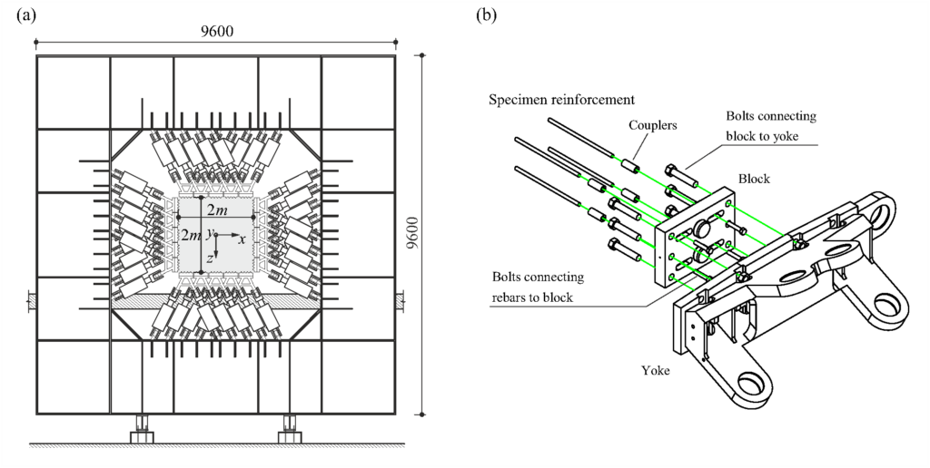
A total of 10 tests on orthogonally reinforced concrete shell elements were conducted. The shell elements, representing a part of a box-girder web, were subjected to combinations of homogeneous loading and imposed deformations, defined such that the boundary conditions imposed to the web by the overall part of the bridge structure were appropriately considered. The tested parameters, included the reinforcement ratio, the kinematic restraints and the loading sequence. In order to study the effect of the web’s stiffness degradation on the transverse bending moment distribution in a transverse section of the bridge, a so-called hybrid test was also conducted. In this test, a finite element model, which was continuously updated with the actual bending stiffness of the physical specimen, reflected the global behaviour of the transverse bridge section and accordingly determined the load to be applied.

What were the main experimental findings?
The results of the experimental campaign confirmed the basic assumption of the majority of existing rigid-ideally plastic models that the compression field responsible for the transfer of longitudinal shear will indeed shift laterally towards the flexural compression side of the web. The flexural compression acting on the shifted compression field together with the overall generalised reactions acting on the web, have a favourable effect on the web’s capacity against the combined loading. In all tests on members with very low stirrup reinforcement ratios, stirrup rupture was found to be the governing failure mode. This brittle failure mode, which occurred before a significant utilisation of the concrete had taken place, limits the applicability of existing models that do not explicity check the deformation capacity of the member. The experimental results therefore highlight the importance of comparing deformation demand to deformation capacity when assessing members with very low vertical reinforcement ratios.
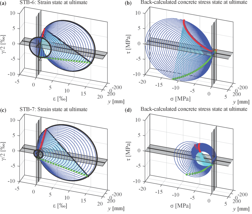
The conducted hybrid test, which accounted for system behaviour, confirmed that the redistribution of bending moments in a box-girder is favourable for the bearing capacity of the web against combined in-plane shear and transverse bending, provided that all adjoining structural elements (the deck and the bottom flange of the section) exhibit sufficient reserve capacity to accommodate the additional load.
Therefore, considering the system behaviour in the assessment of existing bridges can lead to a mitigation of required strengthening measures, or, if such measures are still deemed necessary, greatly simplify them by increasing the stiffness of the deck instead of performing more complicated strengthening measures.
How can existing methods be extended to include a check of the deformation capacity (while retaining the simplicity of application of those models)?
The extension of existing models to enable the check of the deformation capacity requires the consideration in their formulation of more complicated approaches for the modelling of the response of concrete and reinforcement (compression softening and tension stiffening in particular). This leads to their formulation becoming highly nonlinear therefore requiring complex iterative algorighms for their solution. In order to obtain a simplified procedure for the determination of the ultimate load, while at the same time respecting the limits of deformation capacity, a graphical approach was developed. This method, makes use of the experimental observations to reduce the problem to two kinematic unknowns and obtains an estimate of the ultimate transverse bending moment and the associated deformation by graphically determining the intersection of the solution space with the target values for the applied in-plane shear. In addition to providing the ultimate load, the method can also be utilised for the study of the system behaviour since it allows the calculation of simplified bilinear bending moment – curvature diagrams of the web at given levels of in-plane shear.
What is the main takeaway for practicing engineers?
In the assessment of existing structures, a great deal of effort is done towards maximising the utilisation of their existing load-carrying capacity. However, in the case of the combined loading under in-plane shear and transverse bending, a more realistic estimation of the transverse bending moment the web will actually be subjected to, is likely to have a greater impact in avoiding unnecessary strengthening measures compared to making maximum use of the existing load carrying capacity without considering a redistribution of load. Therefore, a more detailed study of the system behaviour accounting for the stiffness reduction in the web with increasing load is recommended.
Link zur deutschen Version: Sind Fachwerkmodelle im 21. Jahrhundert noch zeitgemäss?
For those of you who, like me, studied at ETH, the answer to the question posed by the title of this blog entry is obvious: generations of structural engineers acquired knowledge about truss models and stress fields for a good reason, and they still have a key role in my lectures as valuable tools for the design of concrete structures. But you still might be interested to learn why I am very concerned that truss models may no longer be used in the future – and what we have done to counteract the extinction of these methods?
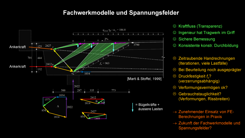
The origins of truss models date back to the early days of reinforced concrete design. However, they were only put on a consistent mechanical basis and used for design decades later: In the second half of the 20th century, a handful of pioneers, including Professor Thürlimann and his assistants at ETH Zurich, dared to apply ultimate limit state design methods to reinforced concrete. To do so, they interpreted truss models as discontinuous stress fields, and these in turn as solutions according to the lower limit theorem of plasticity theory. Truss models thus provide conservative results and make it possible to neglect restraint stresses – which makes them a perfect instrument for design in the ultimate limit state of structural safety.
As self-evident as this may appear, at least to the ETH alumni among us, it was by no means straightforward at the time. Rather, the new theory initially met fierce opposition even within ETH Zurich (see, for example, Basler 1983). In fact, the ductility of reinforcement, and particularly that of concrete, is obviously limited. However, by neglecting the tensile strength of the concrete, providing adequate minimum reinforcement and applying cautious values for the concrete compressive strength, ductile behaviour can be ensured, thus meeting the prerequisites for the application of plasticity theory. As is well known, it is advisable to comply with these design rules in other cases as well. Otherwise, the design becomes semi-empirical and thus orders of magnitude more complicated.
Back to truss models: As already mentioned, they provide a consistent basis for the safe design of concrete structures, and in many cases allow a direct design of the reinforcement for a given applied load. The force flow can be traced and calculations are transparent and easily verifiable. Above all, the engineer is in control of the design and can, for example, choose a practical reinforcement layout. These are all clear advantages in design practice.
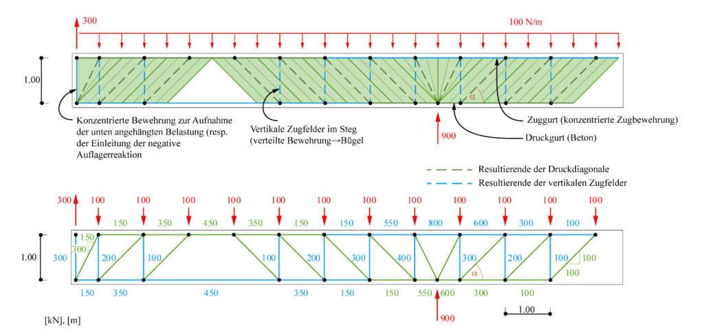
However, truss models also suffer from disadvantages. Since their geometry usually has to be adjusted iteratively and different load configurations have to be investigated, their use as hand calculations is often time-consuming in practice. In addition, they are not directly suitable for determining deflections and crack widths in service conditions, for which other models must be employed, and the dependence of the concrete compressive strength on the transverse strains stipulated by modern standards further complicates the manual development of truss models.
Hence, there is a clear tendency in practice to use any of the user-friendly software packages available today for structural analysis and design based on the finite element (FE) method, which can be used for safety and serviceability limit states – which often results in impractical and uneconomical reinforcement, but can be automated and is thus very efficient.
Unfortunately, the latter does not apply to manually developed truss models and stress fields. If these weaknesses of truss models are not eliminated, there is a genuine risk that they will soon be used only in classrooms – and perhaps as a visual tool for form-finding and tracing the flow of forces in conceptual design. I was already aware of this when I was still in industry, and I also knew how to counteract this development, as my predecessor had already proposed the solution more than 30 years ago (see quote): truss models must be implemented in user-friendly computer programs without compromising their advantages – transparency and control over the design.
Recent advances in computer development indicate that there might be much better ways of using the unique capabilities of computers to assist reinforced concrete designers in the future. There is a considerable potential for applying interactive computer programs with graphical input and output that could replace the traditional drawing board and pocket calculator methods for developing truss models. Apart from ultimate strength considerations, such programs would allow us to investigate the deformations in the cracked state by taking appropriate truss member stiffnesses into account.
Peter Marti: “Truss Models in Detailing,” Concrete International, Vol. 7, No. 12, Dec. 1985, pp. 66-73
However, the times were far from ripe for the implementation of this visionary idea. The first programmes for rigid-perfectly plastic stress fields (e.g. Hajdin 1990) were not very user-friendly. Neither these, nor the programmes developed soon thereafter for plastic design on the basis of linear elastic FE analyses (e.g. Despot 1995) were capable of investigating serviceability nor deformation capacity.
Similarly, when the first programmes for automated design of reinforced concrete with truss models were developed at the beginning of the 21st century, they did not succeed in practice. These discontinuous models ultimately failed in determining the concrete compressive strength and member stiffnesses in an automated and reliable way.
However, the EPSF programme developed at EPFL later indicated that the use of continuous stress fields simplifies this considerably (see Fernández Ruiz und Muttoni 2007). Essentially, EPSF is a simplified FE calculation. The programme is available free of charge, but requires knowledge of Java script and is of limited use for investigations of serviceability criteria and deformation capacity, since it neglects tensile stiffening and presumes linear elastic-ideal plastic material behaviour.
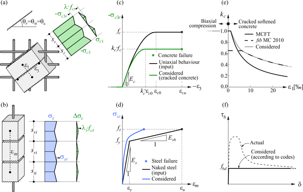
But actually, the implementation of more realistic material laws is straightforward, and in particular the tension chord model developed by Viktor Sigrist and Manuel Alvarez (Marti et al. 1998) is perfectly suited for this. On the one hand, the stiffening effect of the concrete between the cracks is captured in a mechanically consistent way, and on the other hand, the ultimate load is independent of the tensile strength of the concrete, thereby ensuring the link to limit analysis design methods.
When the Czech software company IDEA StatiCa contacted me shortly after my return to ETH Zurich to jointly develop “a tool for automated truss models”, I thus suggested exactly this: To link continuous stress fields with the tension chord model. In the meantime, the Compatible Stress Field Method (CSFM) has emerged from that idea, and the IDEA StatiCa Detail software, which is based on it. IDEA StatiCa Detail is available worldwide, including Switzerland (https://www.ingware.ch/produkte/statik-und-dynamik/idea-statica-detail/idea-statica-detail.html).
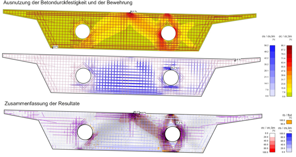
Being a commercial software, IDEA StatiCa Detail (after expiry of the evaluation licence) is not available for free. In exchange, however, it is very user-friendly and powerful. The basic principles and the results of its validation on numerous examples are compiled in a Verification Book, and I recently presented the programme – with a more extensive historical review of the development of stress fields and some application examples – at a training session (click here for the Youtube video).
Neither I personally nor ETH Zurich have any financial interest in the distribution of IDEA StatiCa Detail. Our advantage is immaterial: we hope to contribute to the preservation of the endangered species of truss models and stress fields. Whether you share this concern or are simply looking for an efficient tool for the design of reinforced concrete structures with stress fields: We would be pleased if you would give the programme a try.
Walter Kaufmann
Link zur deutschen Version: Bindeglied zwischen Hochschule und Praxis im konstruktiven Ingenieurbau
Are you a professional engineer, curious about recent developments in structural engineering at ETH Zürich? A Bachelor’s student in civil engineering, wondering if you should specialise in structures at our department? Or a structural engineer interested in pursuing a doctorate in one of our research areas? Or found this blog for other reasons? No matter why you are reading these lines: Welcome to the new blog of the Chair of Concrete Structures and Bridge Design at ETH Zurich!
Soon, you will find posts on a variety of topics here, such as recent findings and publications, activities in commissions, ongoing experimental research, new teaching content or reviews of exams. We will also share our thoughts and opinions on current relevant topics. Thereby, we wish to provide information on our activities and generate a platform for exchange and discussion in our domain.
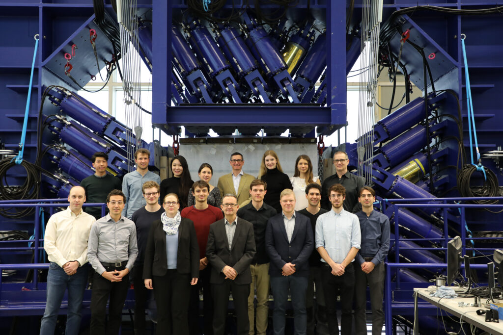
In this introductory post, I want to introduce you to our main activities and explain why we consider starting this blog a necessity. Actually, the latter became obvious to me only recently: When I returned to ETH Zurich in 2014, after having spent more than 15 years working as a structural engineer, I had strong links to industry. Taking these connections for granted, I never imagined starting social media activities to foster the exchange with professional engineers. However, over the past years, I became increasingly aware that my former colleagues had no idea – or at most, a very vague and often wrong one – of our activities in research and teaching.
A while ago, a good friend and highly competent structural engineer bluntly told me that he, and most engineers in industry, had no clue about what was happening “on the Hönggerberg” (for non-ETH graduates: this is where we are located). I then asked my group members if they had received similar feedback from their fellow graduates active in industry, which they confirmed. We then started discussing possibilities to improve this situation and eventually, the idea of this blog was born.
But after all, what are these activities of our group that we want to let you know about? Teaching, research, and service.
Personally, I consider teaching as my most important duty, although an ETH professor’s academic reputation primarily depends on achievements in research. Actually, teaching at ETH is no duty, but rather a pleasure: Having the opportunity to teach bright, motivated young people is a privilege, and one of the most gratifying tasks imaginable.
According to the annual teaching evaluation by the students, our courses are among the most demanding of the department, which is no coincidence: I am convinced that students like to be challenged, rather than bored (which is also confirmed by the evaluation results). We strive to promote critical thinking and self-motivated learning which is not straightforward in these times when credit points being the currency of higher education.
More detailed information on how we try to accomplish this, and about our teaching in general, will follow in upcoming posts. If you are curious in the meantime, you may want to have a look at our e-learning platform https://concrete.ethz.ch/ and perhaps even check out the interactive apps https://concrete.ethz.ch/applikationen/.
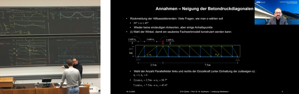
As you might presume given my industry background, our research focuses on questions that we find relevant and practically important. It covers innovative topics but also includes what an eminent colleague once termed “bread and butter” topic research: Investigations of the behaviour of conventional concrete structures.
This is a necessity since the mechanical behaviour of concrete structures is far from being fully understood – which may be difficult to understand given the vast amount of existing concrete structures. For sure, we are able to design safe and efficient concrete structures today, particularly based on the lower bound theorem of plasticity theory (more on this in my next blog post).
However, when assessing the structural safety of existing structures, dimensioned and detailed decades ago using semi-empirical design rules, our modern design methods are rarely expedient, since these structures do not comply with their prerequisites.
Furthermore, existing structures are often subjected to combined loading, making the assessment of their real load-bearing capacity very challenging. Consequently, many existing concrete structures are considered structurally deficient.
However, strengthening or replacing a huge amount of structures without being sure whether this is really necessary is certainly not sustainable. Hence, a better understanding of the mechanical behaviour of concrete structures is essential to reduce the environmental impact of the building industry. Honestly, I think that it is even more urgent than the development of innovative, sustainable solutions.
Nonetheless, we are also doing the latter, and in either case, we typically combine mechanical models with large-scale experimental testing and computational analyses. You will find more information on our research fields and methodologies on our website https://kaufmann.ibk.ethz.ch/. They will be a main part of the future content of this blog.
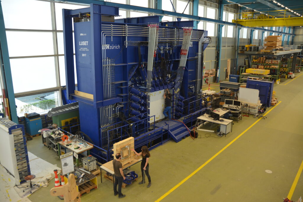
Last but not least, we also provide services to industry and society. These activities range from top-level consulting – not competing with, but complementing industry expertise – to active participation in professional societies, expert bodies, and code commissions. Thereby, we want to contribute to the solution of our society’s challenges. We will also talk about these activities in future posts.
Rather, we want to generate a platform for exchange and discussion in structural engineering.
As said, the goal of this blog is not only to provide information on our activities but also to generate a platform for exchange and discussion in structural engineering. To this end, we encourage you to send us your feedback, be it positive or negative. We are also planning to include guest posts in this blog, and invite you to contact us if you are interested in authoring a contribution.
We hope that you like the idea of this blog, and will become a regular reader. Please let us know your opinion and wishes in the comment section below.
Walter Kaufmann