Link zu der deutschen Version: Herstellung eines CFK-vorgespannten Bahnbrückenprototyps.
Some time has passed since the last blog post on this topic, and the project team consisting of SBB, alphabeton AG, HSLU, Empa and ETH has made considerable progress towards their goal of prestressing railway bridges in the span range of 2-10 m with carbon fibre-reinforced polymer (CFRP) rods. The most recent progress is the construction of a 1.7 m x 6.5 m biaxially CFRP-prestressed prototype representing a sector (four instead of nine longitudinal girders) of an overpass with 6 m span. The prestressing is designed to avoid cracking under service loads (LM1). Figure 1 shows the basic idea of the bridge system with the stainless reinforcing steel and the sand-coated CFRP prestressing rods.
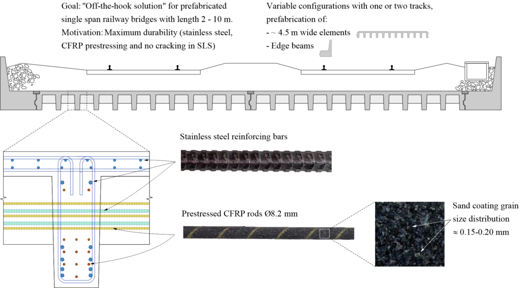
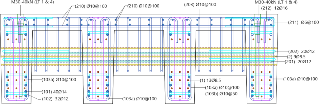
Figure 2 shows the reinforcement detailing in the cross-section of the prototype. It contains the following elements:
- CFRP prestressing rods (longitudinal prestressing Pos. (1), transverse prestressing Pos. (2))
- Bending reinforcement of the longitudinal (101) and transverse (201) girders (1.4362 duplex steel)
- Stirrups and bridge deck reinforcement (made out of B500B steel in the prototype due to cost)
- T-head bars in the intersections of the longitudinal and transverse girders (Pos. 212)
- Lifting anchors in the outer girders
Two important changes to the concept and the production process have been made since the last blog post:
- Instead of ultra-high performance concrete (UHPC), high performance concrete C80/95 was employed. Preliminary tests have shown that this concrete is sufficient to anchor the pretensioned CFRP rods via bond – at a significantly lower cement content.
- The production was staged: The longitudinal girders (two behind each other pretensioned with the same rods) were cast in a first step. After the production of the four longitudinal girders, they were placed next to each other to cast the prestressed transverse girders (prestressing rods and reinforcement through recesses in the longitudinal girders) and the deck slab.
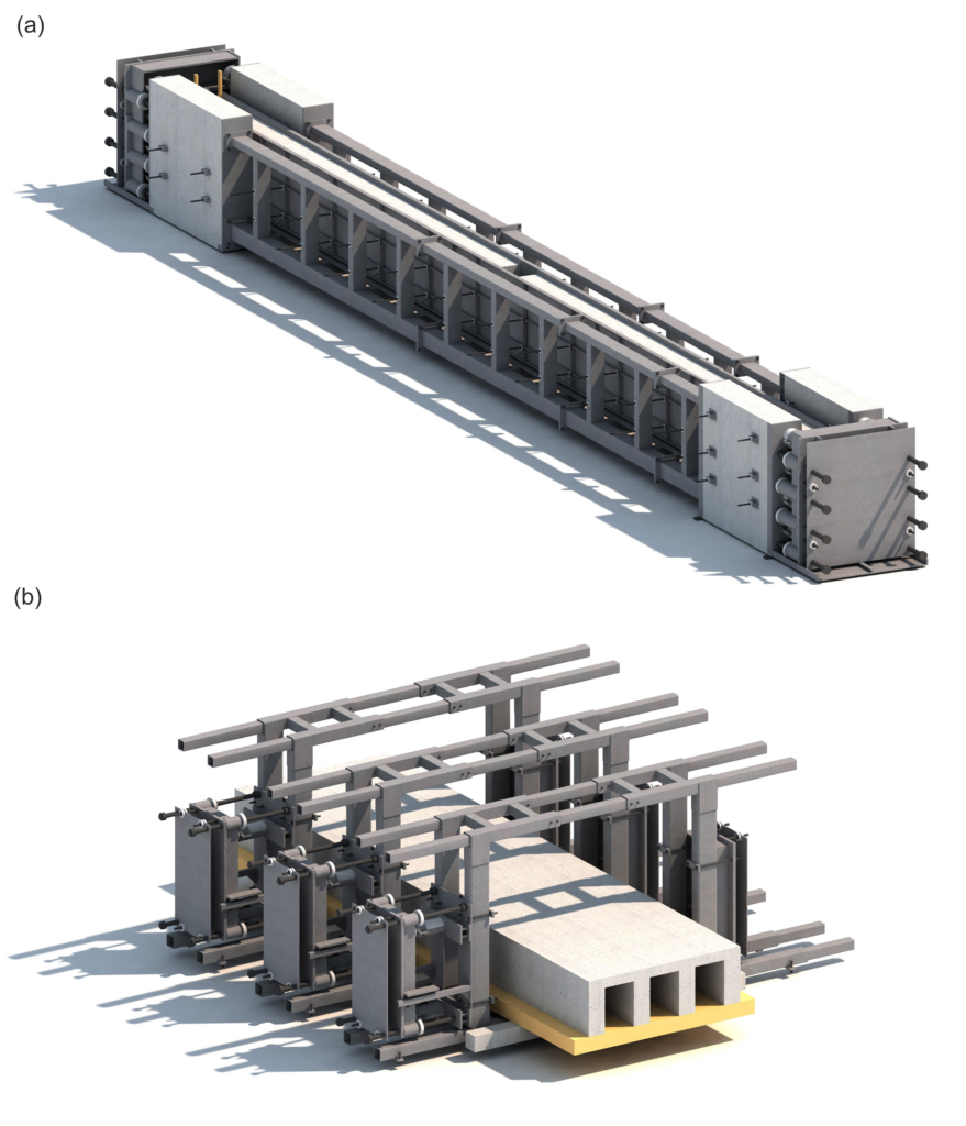
Extensive technology development and preliminary works were required for the production of the prototype. The first challenge was the design of the tensioning frames for pretensioning the longitudinal and transverse girders, realised by Prof. Dr. Albin Kenel and Martina Rohrer, HSLU. Figure 3 shows renderings of the tensioning frames. The frame for the longitudinal girders (Figure 3 (a)) is in total approximately 14 m long (the modular design enables arbitrary lengths <14 m) and designed for a total prestressing force of 2.8 MN. The frames for the transverse direction (Figure 3 (b)) have to resist considerably lower forces (~0.8 MN). All frames have identical systems: The CFRP rods are anchored in perforated plates, which are pushed with hydraulic jacks to reach the desired prestressing force in the rods. Subsequently, the girders are cast around the pretensioned rods, which are released when the concrete has reached the required strength.
The second challenge was the development of the wedge anchors for the CFRP rods, which are difficult to pretension due to their anisotropy. The anchor system (developed by Prof. Dr. Giovanni Terrasi and Valentin Ott, Empa) consisting of a steel barrel and three polymer wedges is able to reliably anchor 55 kN per rod (equivalent to 1041 MPa on a nominal diameter of 8.2 mm). Figure 4 shows (a) a single anchor, (b) the hydraulic pressing of the wedges into the barrel, and (c) the arrangement of the anchors on the perforated end plate for the production of the longitudinal girders.
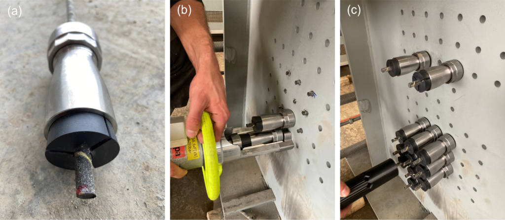
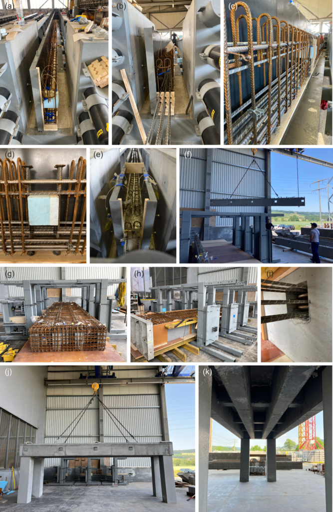
Figure 5 shows pictures of the production in the prefabrication plant of alphabeton AG:
| (a) | Reinforcement cages of the longitudinal girders in the tensioning frame. The cages had to be manufactured very precisely to avoid any contact between reinforcing steel and CFRP rods which would lead to (i) uncontrollable deviation forces and in the worst case rupture of the rods, and (ii) increased risk of galvanic corrosion of the reinforcing bars. |
| (b) | Reinforcement cages with the lower layers of the CFRP prestressing rods with the perforated formwork for the girder ends. |
| (c) | Reinforcement cage with CFRP prestressing rods. |
| (d) | Detail of the recesses with the T-head bars in the intersections of the longitudinal and transverse girders and specifically for this purpose (at Empa) 3D-printed spacers which could be mounted onto the longitudinal reinforcing bars. In this manner, the required precision of the recesses for the transverse prestressing could be assured. |
| (e) | Longitudinal girders in the scaffolding after casting. |
| (f) | Placement of the longitudinal girders in the frames for transverse prestressing. |
| (g) | Reinforcement of the end girders and the deck slab. |
| (h) | Wedge pressing for the transverse reinforcement. Note that massive steel plates were mounted to the frames during tensioning to prevent uncontrolled projection of the wedge anchors in case of failure of a CFRP rod (see Figure 3). |
| (i) | Detail of the transverse prestressing in the recesses of the longitudinal girders. |
| (j) | Finished prototype: side view. |
| (k) | Finished prototype: view from below with longitudinal and transverse girders. |
In conclusion, the production of the prototype was successful. Preliminary fibre-optical strain measurements on the CFRP rods show that the prestressing forces are anchored on less than 200 mm via bond, which shows that pretensioning with sand-coated CFRP rods works. The “lessons learned” until now include the design as well as the implementation. Static efficiency and complexity of the production must be carefully balanced; a little more space between CFRP and reinforcing bars would have facilitated the production substantially. Pretensioning the CFRP rods is demanding and requires – besides tailored hardware such as the tensioning frames and the wedge anchors – very precise work, especially during manufacturing of the reinforcement cages. From the point of view of the project team, alphabeton AG has provided the proof of concept for the production, however, the path towards constructing the first CFRP-prestressed railway bridge is still long… Stay tuned!
Andreas Näsbom