Link zur deutschen Version: Duktilität und Rotationsvermögen im Stahlbetonbau
What is ductility? Why do we need it?
Ductility is a ubiquitous concept in structural engineering and structural concrete, the field treated specifically by this post.
In seismic engineering, some well-known authors have proposed definitions such as those given below.
Der Begriff Duktilität bezeichnet die Fähigkeit eines Tragelementes oder Tragwerks, sich nicht nur elastisch, sondern unter Aufrechterhaltung des Tragwiderstandes auch plastisch zu verformen.
(Paulay, Bachmann, Moser 1990 Erdbebenbemessung von Stahlbetonhochbauten)
The term “ductility” in structural design is used to mean the ability of a structure to undergo large deformations in the postelastic range without a substantial reduction in strength.
(Park 1991 Ductility of Structural Concrete)
The definitions have their origin in seismic engineering and aim to avoid excessive damage under large imposed inelastic deformations and thus in some cases, accept a slight loss in strength or softening. This is uncommon and unconservative in structural engineering, where most considered actions are force-driven and failure occurs at maximum load.
Paulay, Bachmann and Moser (1990) propose to differentiate between different types of ductility on different scales, i.e. strain ductility on the level of material, curvature ductility on the level of the cross-section, rotation ducility for plastic hinges and deformation ductility of the structural system. The ductility is defined as the ratio of the considered quantity (e.g. strain, curvature) at failure and at yielding.
In structural engineering, ductility is defined as follows by the SIA 260 (2013):
Durch irreversible Verformungen und Energiedissipation charakterisiertes, in der Regel auf die Grenze des elastischen Verhaltens bezogenes plastisches Verformungsvermögen.
In structural engineering, ductility is required to apply the Theory of Plasticity and thus redistribute stress resultants and neglect initial stress states. This idea is also reflected by codes such as the Swiss SIA or Eurocodes. The SIA 262 (2013) standard specifies that the Theory of Plasticity can only be applied if ductile behaviour is guaranteed. The redistribution of stress resultants is allowed if the ratio of x/d is limited, ductile reinforcing steel and no high-strength concrete is used. The Eurocodes allow neglecting thermal effects, differential settlements and shrinkage if an element’s ductility and rotation capacity are enough. There is no indication on determining whether the ductility is sufficient, but a check for the rotation capacity is proposed (see second section).
While the exact definition is not unanimous, most authors agree on the reasons why we should strive for ductile structures. The arguments can roughly be grouped into the following two main ideas:
- Prevention of unforeseen failure (Announcement of failure, achieving robustness, safety from earthquakes or other extraordinary events)
- Redistribution of internal actions (using bending moment distributions other than elastic on, neglecting self-equilibrated stress states)
A well-known example where ductility prevented failure is the Reussbrücke Wassen which survived large settlements of its pier in a flood event in 1987 and could be repaired (Figure 1).

Is structural concrete ductile? How can we be sure in design?
As seen above, structural concrete can be ductile. The question is to determine in advance whether it is ductile enough. Two approaches are presented here.
In Swiss building practice ductility is achieved by relying on existing knowledge about favourable construction measures. Measures include the choice of adequate, proven building materials, the placement of minimum bending reinforcement and the use of stirrups to avoid brittle shear or compression chord failures. The measures rely on experience and experimentally validated results, which is also their main downside: while they’re very efficient in standard cases, they limit, e.g. the use of new materials.
The SIA 262 allows the redistribution of stress resultants without checking deformation capacity if the depth of the compression zone is limited and the steel ductility class is at least B500B and the concrete compression class is lower than C50/60. Eurocode 2 contains similar stipulations but allows high-strength concrete with a stricter limitation of the compression zone depth. From this, one may deduce that structures fulfilling these requirements are ductile.
If these conditions are not met, one needs to check whether the expected rotation capacity of plastic hinges is larger than the rotation demand. While this isn’t a direct check of ductility, it aims to ensure that the plastic rotations required for moment redistribution up to a design load level can take place without failure. In this post, I’m presenting and comparing two ways to estimate the rotation capacity.
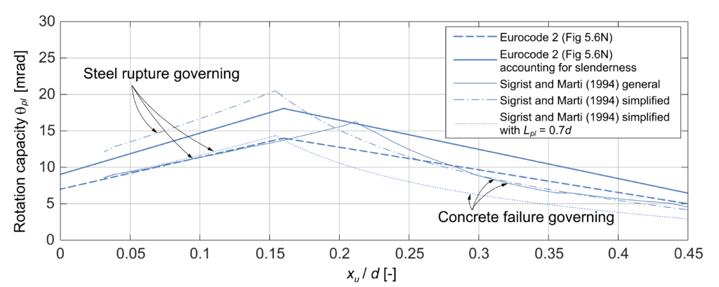
Eurocode 2 (2004) proposes bi-linear relationships for the plastic rotation capacity as a function of xu/d, where xu is the depth of the compression tone and d is the static depth. The relationships distinguish between normal-strength and high-strength concrete and steel of classes B500B and B500C. They can be multiplied by a factor accounting for the shear slenderness. The main disadvantage of this method is that it is a “black box”, so it is hard for engineers to judge the plausibility of their design.
Sigrist and Marti (1994) propose a general method and a simplified design procedure for the rotation capacity based on the Tension Chord Model. The simplified method calculates the mean plastic curvature at failure and multiplies it with an assumed plastic hinge length equal to the static depth d. The authors provide two analytical expressions for the mean plastic curvature, depending on whether rupture of the reinforcement or failure of the concrete compression zone is governing. At low or moderate mechanical reinforcement ratios, reinforcement rupture is the governing failure mode and at comparatively high mechanical reinforcement ratios, failure of the concrete compression zone is governing.
The general method is not presented in detail here. It follows the same idea of determining the steel strains in the plastic zone. It considers the variation of the tension chord force, which can be used to determine the length of the plastic hinge, and bending moment redistributions as the plastic hinge yields.
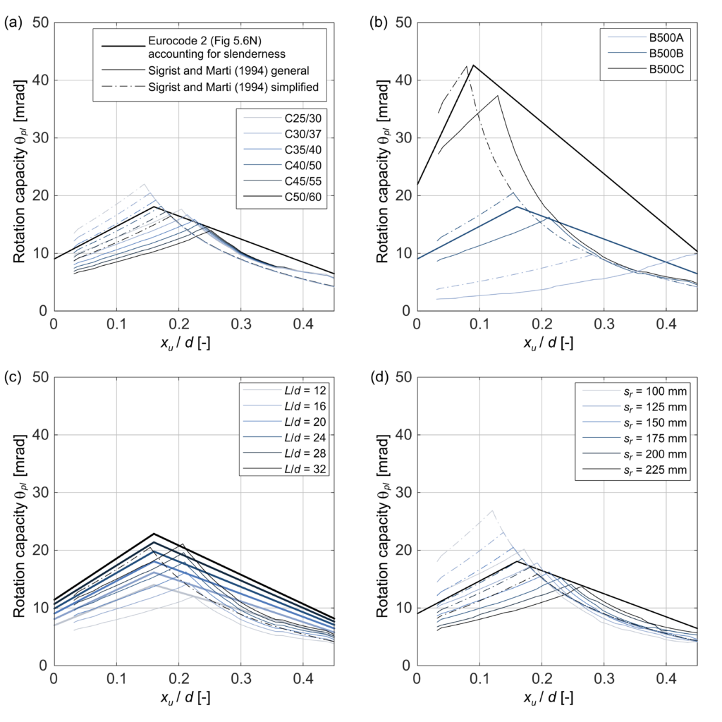
Figure 2 shows a comparison of the three presented methods for an assumed two-span girder with a static depth d of 1200 mm under a uniformly distributed load. The base case considers concrete C30/37, reinforcing steel B500B, slenderness L/d = 20 and a crack spacing of 150 mm. In Figure 3, these parameters are varied one at a time. The curves start at the minimum reinforcement to avoid brittle failure at crack formation.
The bi-linear shape of the curves proposed by the Eurocode reflects the shape obtained by the methods based on the Tension Chord Model, which represents governing steel or concrete failure. The difference between the models proposed by Sigrist and Marti (1994) at low mechanical reinforcement ratios is mainly due to the estimation of the plastic hinge length in the simplified method: If a hinge length of Lpl = 0.7 d instead of Lpl = d is chosen, the curves nearly coincide. The unknown length of the plastic hinge is one of the main disadvantages of the simplified method.
Figures 3 (a) to (d) show the influence of the concrete class, the steel ductility, the slenderness and the crack spacing, respectively.
The Eurocode provides a single relationship for the rotation capacity of concrete classes < C50/60. The models based on the Tension Chord Model predict a decrease of the rotation capacity for higher concrete strength if the reinforcement rupture is governing and no influence if concrete failure is governing. While this may seem counterintuitive initially, it can be explained by the relation of the bond stress and the concrete tensile strength according to the Tension Chord Model. Higher bond stress means a more considerable influence of tension stiffening and thus a lower mean steel strain over the crack element and a lower rotation capacity.
Using high ductile steel the models predict a higher rotation capacity, as expected, and concrete failure becomes governing at lower mechanical reinforcement ratios. The Eurocode allows multiplying the proposed bilinear relationship by a factor kλ, accounting for the slenderness of the structure. The general method by Sigrist and Marti (1994) shows a similar increase in rotation capacity with slenderness, but the simplified method does not consider slenderness.
The methods based on the Tension Chord Model reflect that a larger crack spacing has a negative impact on ductility. The bilinear curve proposed by the Eurocode does not consider crack spacing. This may also be an advantage considering the difficulty of crack spacing estimates due to its stochastic nature.
Let’s summarise the main conclusions from the comparison of the methods and the parameters studies
- The plastic hinge length has an important influence on the results of the simplified method proposed by Sigrist and Marti (1994), but it is hard to estimate in advance.
- The influence of slenderness is not included in the simplified method.
- The Eurocode gives tendentially higher estimates of the rotation capacity when concrete failure is governing because the proposed relationship is linear (compared to the nonlinear relationships of the other methods)
A specific structure design corresponds to a single point in these diagrams. As both the Eurocode and the simplified method by Sigrist and Marti (1994) are very simple to apply, it may make sense to compare both results in practice.
While the difference between the results of the different methods may seem significant, it is essential to note that the scatter between experimental results is also quite pronounced. This justifies the use of a simple approach (instead of a refined one) for checking the deformation capacity but calls the general validity of such checks into question.
A direct check of ductility (as a ratio of e.g. the rotation at failure and yielding) is not performend for static problems. While the calculation of the rotation ductility in plastic hinges is discussed in expert literature, hardly no informations is provided on the ductility requirement.
What’s the relation between the check of deformation capacity and ductility?
While structural engineers are generally familiar with the concept of ductility, it is often confused with other, related concepts such as deformation capacity and demand.
The definitions in the SIA 260 state that ductility is deformation capacity characterised by irreversible deformations and energy dissipation, wherein deformation capacity comprises the elastic and plastic deformations of a structure up to failure. Thus a ductile structural element is one that can support large inelastic deformations while dissipating energy, i.e. not softening before it fails. The concept of ductility is not directly related to the acting loads or the deformation demand.
In contrast, the check of deformation capacity compares the deformation capacity with the deformation demand in a design situation, according to Eurocode 2. Suppose the stress resultants in general or in a region are low. In that case, the check of deformation capacity can be fulfilled even if the deformation capacity in itself is not particularly high. This has positive and negative consequences. On the one hand, providing a high deformation capacity in regions that will most likely never reach yielding seems unnecessary. On the other hand, unforeseen loads or self-equilibrated stress states may lead to an unexpectedly large deformation demand, in which case a lack of deformation capacity may prove fatal.
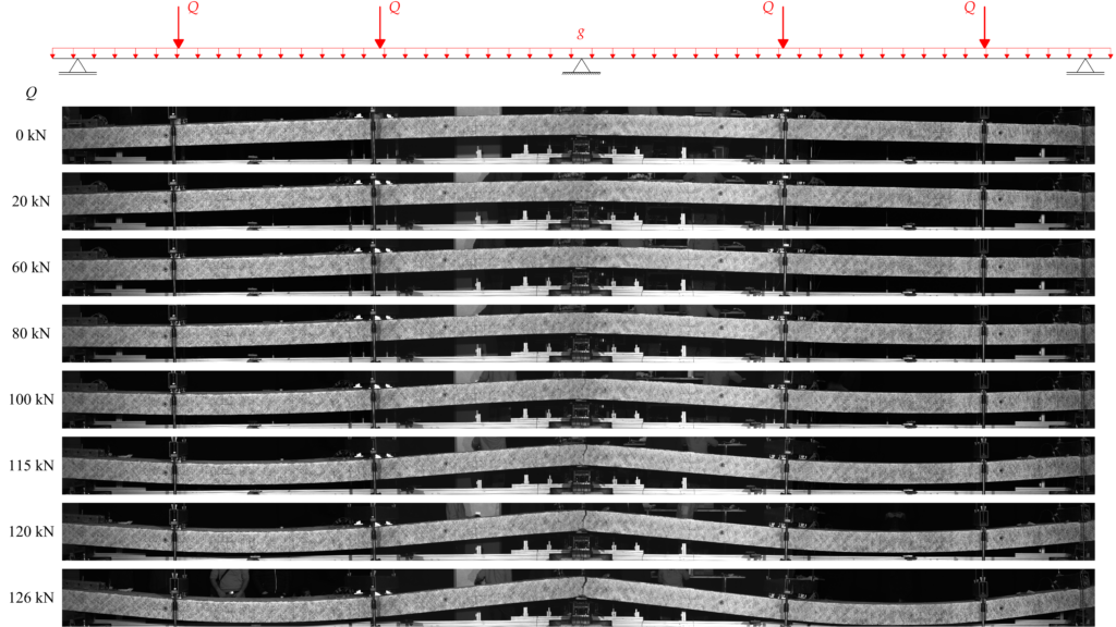
One of the main difficulties in assessing the deformation demand is that self-equilibrated stress states influence it. Consider the example of an experiment on a two-span slab strip shown in Figure 4. Before starting the experiment, the initially plane specimen is subjected to a self-equilibrated stress state by moving the supports. This creates a hogging shape at a load of 0 kN, as seen in Figure 4. It is intuitively clear that the rotation demand at the intermediate support is higher in this case than if the specimen had not been subjected to an initial, self-equilibrated stress state. Consequently, unfavourable self-equilibrated stress states need to be considered to determine the rotation demand.
In the extreme case, one might require that the deformation capacity is larger than the deformation demand until the ultimate plastic load, associated with a plastic mechanism, is reached. That way, the deformation capacity is sufficient for any self-equilibrated stress state. Unfortunately, the SIA 262 does not provide information on how exactly to conduct a check of the deformation capacity and which actions to consider in the determination of the deformation demand.
What’s the conclusion from all of this? Where do we want to go?
This blog post introduced the topic of ductility in the design of reinforced concrete structures subjected to static loads and presented two simple methods to estimate the rotation capacity to check the deformation capacity in practice. Then it explained the relation between the concept of ductility and the deformation capacity check.
One current issue is that the SIA 262 does not include methods to provide ductility in structures that do not comply with the usual construction rules. If, e.g. reinforcing material that does not comply with ductility classes B500B or B500C is used, the redistribution of stress resultants is only possible with a check of deformation capacity. This is a severe restriction for innovative materials and fabrication technologies, e.g. for new types of reinforcement or digital fabrication, because the presented methods for the estimation of the rotation capacity are limited to specific applications: they work well on one-way carrying structures but cannot be applied to two-way carrying slabs for example. Furthermore, the check of deformation capacity is challenging due to the dependence of the deformation demand on self-equilibrated stress states.
Current research aims at finding a strategy to design structures composed of materials with low ductility, softening or even brittle behaviour in certain regions, where they don’t endanger the overall ductility.
For this purpose, the ideas of Capacity Theory may be applied to elastic-plastic systems, thus designing the structure such that failure occurs in a region with a high deformation capacity. A similar approach is the background of code provisions to avoid brittle shear failures in favour of bending failures.
Simultaneously an experimental series on two-span slab strips is carried out in collaboration between the chair of Concrete Structures and Bridge Design at ETH Zurich and the Institute of Civil Engineering (IBI) at the Lucerne University of Applied Sciences and Arts. Figure 4 shows an experiment on a slab strip reinforced with steel that has a large ultimate strain but hardly any strain hardening over a major part of the inelastic range. This is one in a series of 21 planned experiments with metallic reinforcement types, different ductility and strength levels, and non-metallic reinforcements. The ongoing research should aid the use of innovative materials and fabrication technologies and generally improve the understanding and awareness of ductility, deformation capacity and deformation demand in structural concrete.
Nathalie Reckinger
Comment this blog post on LinkedIn or Instagram