Link zur deutschen Version: Langzeiteinflüsse bei der Bemessung von monolithisch verbundenen Pfeilern für vorgespannte Träger oder Platten
This blog post is about a technically challenging topic: how to consider long-term effects (shrinkage and creep) in the design of piers monolithically connected to a prestressed girder or slab. This structural arrangement can be found in monolithic building structures or, more commonly, in prestressed concrete bridges. Therefore, I do not doubt that this will be a topic of great interest if you are passionate about structural design and perhaps even had to deal with it already in your professional practice.
The design of monolithic, i.e., jointless structures is becoming increasingly common in bridge design in Europe. The main reasons for this are, firstly, the desire to eliminate durability problems and reduce maintenance costs, and secondly, that guidelines for the design of such structures are becoming increasingly available. Switzerland is a reference country that has contributed to developing this type of structures, where traditionally, concrete bridges with piers monolithically connected to the deck, and semi-integral or integral bridges (monolithic connection at both abutments) [1] where possible, are preferred [2]. Numerous realisations of jointless bridges [3][4][5][6][7] have been built in Switzerland, and technical guidelines promote integral or semi-integral bridges [1][2] (old reference1Routes Nationales Suisses, Projects Standards de Ponts, Passage Supérieur avec Béquilles en V en Béton Coule sur Place, Departement Federak de L’Interieur, Bern 1972 from the 70s). Given the resulting tendency to build ever longer monolithic jointless bridges, increasingly more accurate and complex calculations are required to reliably design the piers. About a decade ago, I had the chance to contribute to a publication supporting engineers in the design of piers of long jointless concrete structures [8], but that document is limited to building structures, where the slab or girder is not prestressed.
Despite the availability of powerful structural analysis software, analysing statically indeterminate structures subjected to long-term effects remains a challenge. A clear example of this, which we will discuss in this blog, is how to estimate the bending moments due to long-term effects in a concrete pier monolithically connected to a prestressed girder. In this type of structure, a large part of the forces acting in the pier is associated with the deformations imposed to the pier head by the deck, which are relevant in Serviceability Limit States (SLS) and Ultimate Limit States (ULS STR and ULS FAT2Although the imposed deformations (shrinkage and creep) are no cyclic actions, they are relevant in ULS FAT (fatigue failure) for concrete fatigue verifications, which depend on the absolute maximum and minimum concrete stresses.). However, obtaining the internal forces in the pier caused by long-term effects with acceptable accuracy is complex since the stresses vary non-linearly over time (the modulus of elasticity varies with the age of the concrete), the girder and the pier do not creep equally (different creep coefficient, i.e. different concretes and of different ages), and the cracked bending stiffness varies over the pier height and depends on the load history (maximum tensile stress). Thus, in normal engineering practice, to easily estimate the internal forces in the piers, engineers typically consider: (i) reduced pier bending stiffnesses due to cracking (generally constant or linearly variable along the piers), which are calculated by iteration and are different for SLS, ULS STR and ULS FAT verifications, (ii) about 40…50% of the total shrinkage of the deck at infinite time to take into account the long-term effects, but (iii) neglect long-term effects due to prestressing arguing that creep of the pier compensates the increase of the pier head displacement due to creep of the girder.
The first simplification, if done with due engineering judgement, can generally be accepted, but should be complemented by a sensitivity study to cover the uncertainties of the calculations. However, with respect to the second and third simplifications, the following questions inevitably arise: Is this approach appropriate and under what conditions is it valid? What is the background behind it? Is this conservative? Is it necessary to perform a sensitivity analysis to cover uncertainties if this action is decisive for the design?
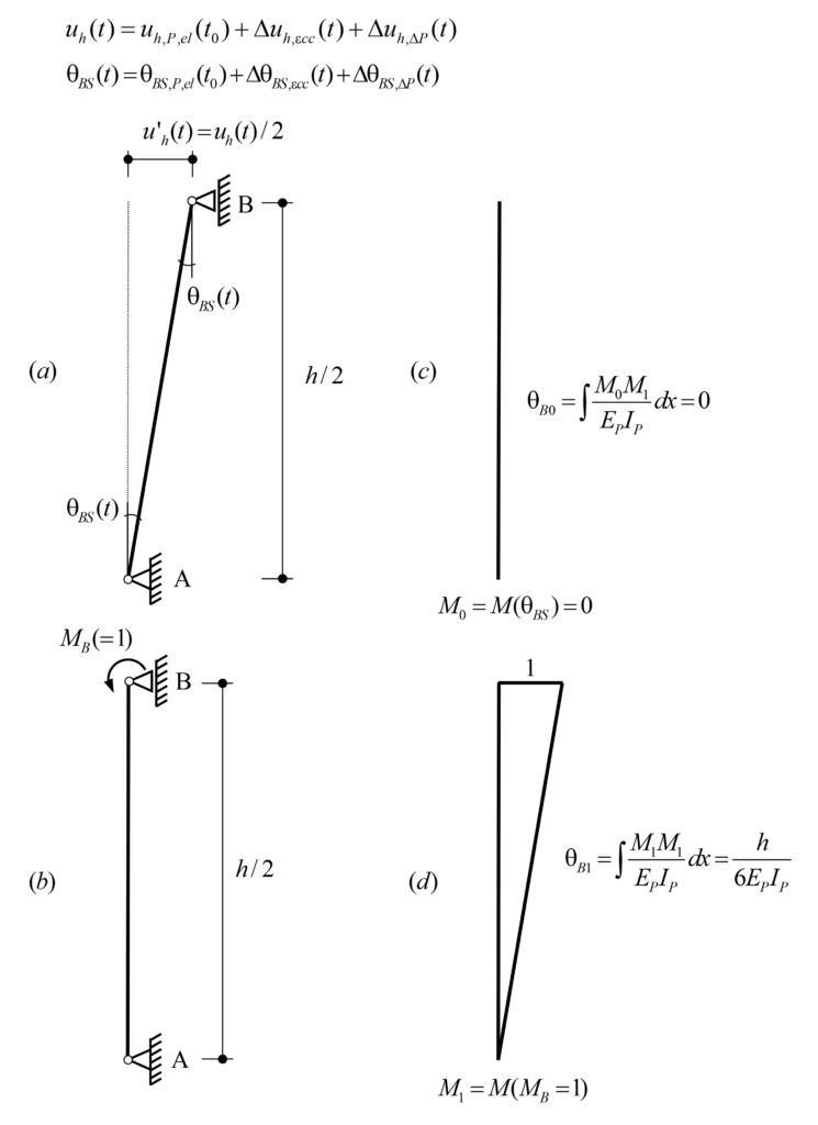
After this introduction, it is time to answer these questions. In the following, you and I (let me involve you in the analysis) will analytically solve the formulated problem, interpret the results and draw some conclusions. The structure to be analysed is shown, in a simplified manner, in Figure 1. The horizontal element represents a prestressed concrete girder, and the vertical one a pier of height h, which is monolithically connected to the girder at a distance LT (expansion length) from the fixed point. The mechanical properties are constant for both elements and are indicated in Figure 1(a). Figure 1(b) and Figure 1(c) show the horizontal displacements of the pier head over time, uh,εcs(t) and uh,P,el(t), caused by the shrinkage εcs(t) and the prestressing P(t) of the girder, respectively. Note that the restraint of the pier to the horizontal displacements imposed by the girder is neglected since, in general, the axial stiffness of the girder is orders of magnitude much higher than the horizontal (bending) stiffness of the pier. Furthermore, according to the equations presented in Figure 1(c), the following assumptions have been made: normal force constant along the girder (no frictional prestress losses) and EPIP<<EGIG, i.e., pier “perfectly” double-clamped. Note that the latter consideration is not suitable for some cases, e.g. building structures where the bending stiffness of the column is not negligible compared to that of the girder or flexible foundations (deep foundations). However, the long-term effects calculated below are formulated independently of the pier and deck stiffnesses, which can be included directly as imposed deformations in finite element analysis (FEA). In addition, the influence of the pier creep on the corresponding (uncracked and cracked) bending stiffness is not accounted into the following calculations, thus, the equivalent reduced bending stiffness of the pier, considering creep and cracking, should be used in the static system.
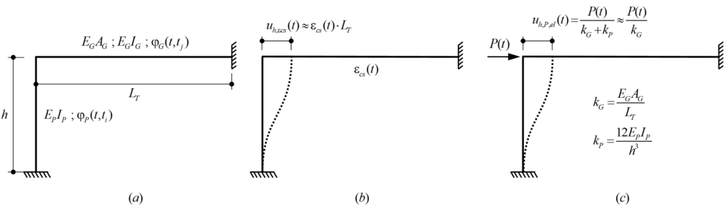
EG: Modulus of elasticity of the girder
EP: Modulus of elasticity of the pier
IG: Second moment of area (area moment of inertia) of the girder
IP: Second moment of area (area moment of inertia) of the pier
φG(t,tj): Creep coefficient of the girder
φP(t,ti): Creep coefficient of the pier
In order to solve the system analytically, the frame structure in Figure 1 is simplified according to Figure 2. To obtain the internal forces in the pier caused by the imposed horizontal displacement uh, the isolated double-clamped pier of height h (Figure 2 (a)) can be replaced by the isolated hinge-clamped pier of height h/2 (Figure 2 (b)). Thus, Figure 2(c) shows the equivalent simplified system to obtain the internal forces in the pier due to a horizontal displacement u’h at the pier head, which is equal to half of the horizontal displacement uh in the original system (Figure 1), i.e. u’h (t)= uh(t)/2. Note that in order to achieve the correct pier head displacement caused by prestressing, the equivalent prestressing force P’ (t) in the simplified system (Figure 2(c)) is equal to half of the prestressing force P(t)/2 in the original system (Figure 1) if the bending stiffness of the pier is neglected to the axial stiffness of the girder, otherwise, it is as follows:

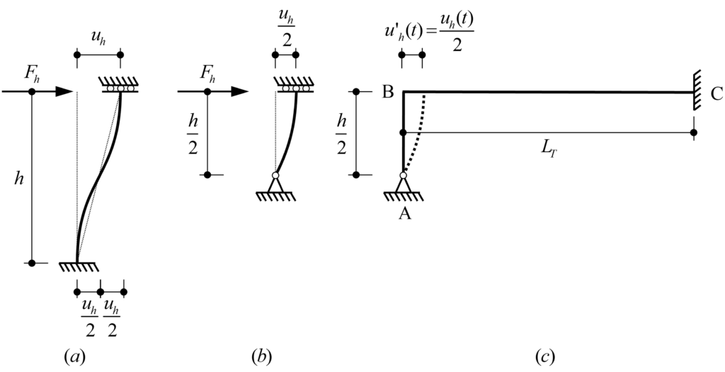
In the following, we isolate the pier of the simplified system shown in Figure 2(c) and solve a system composed of a pier with a single degree of static indeterminacy by using the time dependent force method and formulating the compatibility equations over time, where:
BS (basic system): Fixed rotation in B (pier head) released
RV (redundant variable): Bending moment in B (pier head)
In addition, the time-dependent bending moments at the pier head due to shrinkage and prestressing are calculated separately.
Time-dependent behaviour of concrete pier
1. Shrinkage (time-dependent pier head displacement3Note that the pier head displacements can be treated analogously as settlements in our long-term effects lecture (time-independent or time-dependent).)
Figure 3 shows the isolated pier with the basic system (BS) and the redundant variable (RV) used to determine the bending moment MB(t) by using the force method. Since the bending moment MB(t) varies over time, compatibility at Support B is expressed both at the initial time as well as time-dependent.
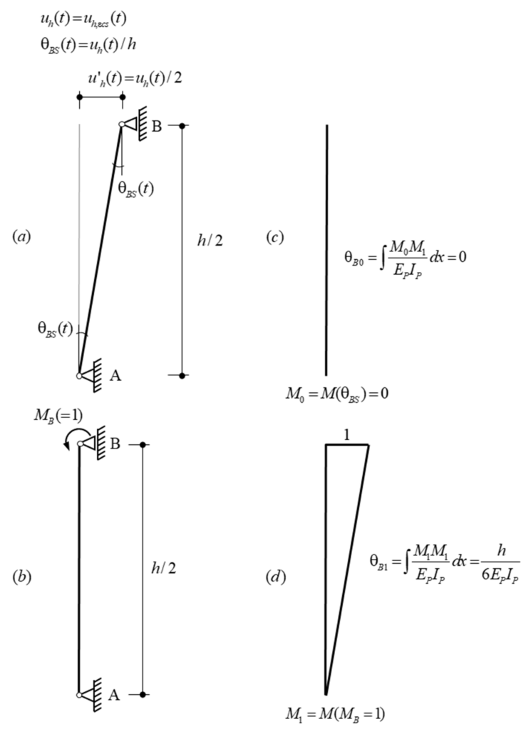
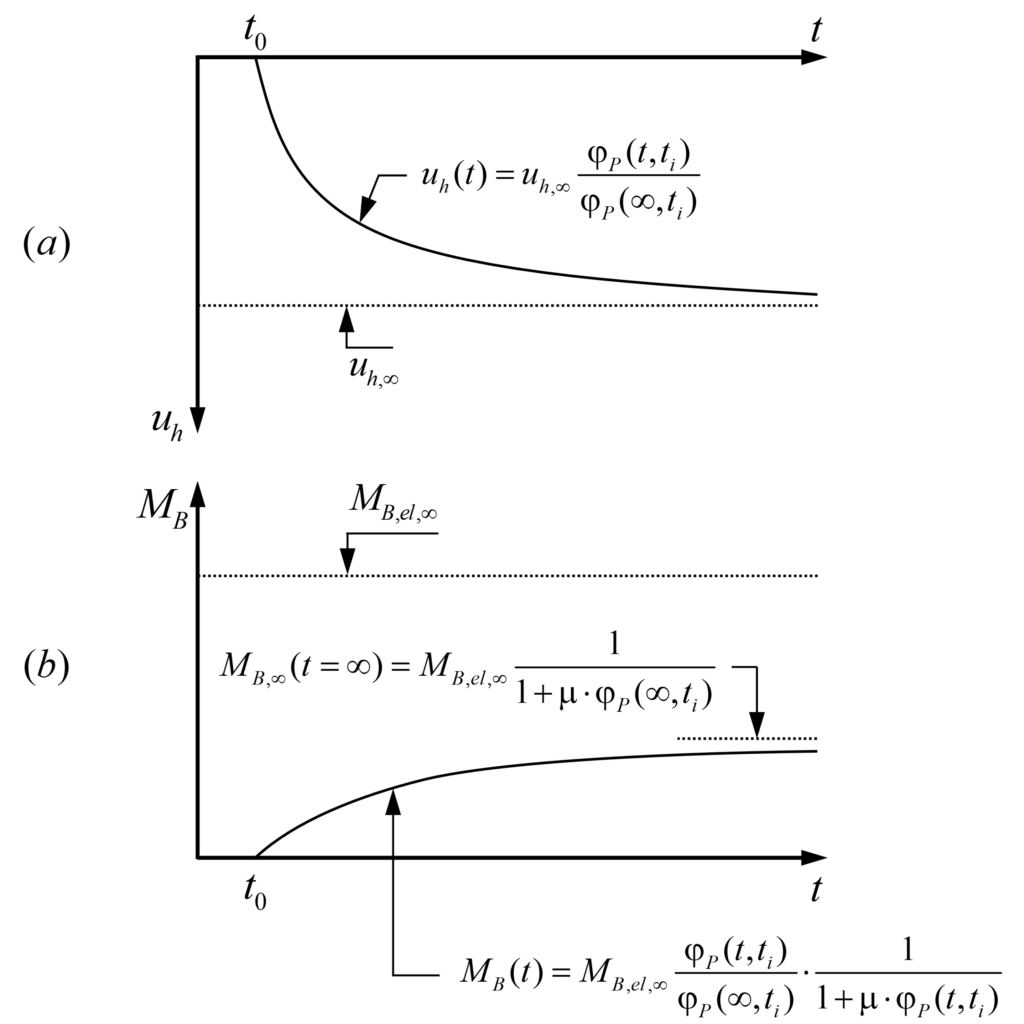
The shrinkage εcs(t) of the girder causes an imposed deformation over time, which generates horizontal displacements uh(t) and bending moments MB(t) at the pier head. At the initial time, the horizontal displacement uh(t0) and the bending moment MB(t0) are both zero (no shrinkage). At any given time t> t0, the girder has shrunk by εcs(t), causing a horizontal displacement uh(t) and the bending moment MB(t), see Figure 4(a) and Figure 4(b) respectively. Assuming that the shrinkage of the girder, and hence, the imposed deformations over time uh(t) are proportional to the creep function of the pier, uh(t) can be expressed as:
![\[{{u}_{h}}(t)={{u}_{h,\infty }}\frac{{{\varphi }_{P}}(t,{{t}_{i}})}{{{\varphi }_{P}}(\infty ,{{t}_{i}})}\text{ (eq}\text{. 1)}\]](https://concrete.ethz.ch/wp-content/ql-cache/quicklatex.com-1533735f2c8fccbff81d0ea338d639e6_l3.png "Rendered by QuickLaTeX.com")
Hence, at infinite time, the horizontal displacement at the pier head reaches the maximum horizontal displacement uh,∞ = εcs,∞·LT (Figure 4(a)). However, as we will see below, the bending moment MB,∞ (t=∞) will be lower than the elastic bending moment MB,el,∞ caused by the maximum horizontal displacement uh,∞ (Figure 4(b)).
The bending moment MB(t) at the pier head can be formulated as follows:
![\[{{M}_{B}}(t)=\cancel{{{M}_{B}}({{t}_{0}})}+\Delta {{M}_{B}}(t)=\Delta {{M}_{B}}(t)\text{ (eq}\text{. 2)}\]](https://concrete.ethz.ch/wp-content/ql-cache/quicklatex.com-a49ed75a91cf83e02d6313b703191b89_l3.png "Rendered by QuickLaTeX.com")
Where ΔMB(t) is the bending moment increment over time due to shrinkage.
Rotation compatibility condition at the initial time t=t0:
Rotation compatibility at the initial time (note that all actions are applied in the basic system (BS)) yields the expression:
![\[{{\theta }_{B}}({{t}_{0}})=\cancel{{{\theta }_{B0}}}+{{M}_{B}}({{t}_{0}})\cdot {{\theta }_{B1}}={{\theta }_{BS}}({{t}_{0}})=0\to {{M}_{B}}({{t}_{0}})=\frac{\cancel{{{\theta }_{BS}}({{t}_{0}})}}{{{\theta }_{B1}}}=0\text{ (eq}\text{. 3)}\]](https://concrete.ethz.ch/wp-content/ql-cache/quicklatex.com-e03f6a33aec51bc4ef804d72502dde5b_l3.png "Rendered by QuickLaTeX.com")
As mentioned above, it is evident that at the initial time, the bending moment at the pier head is zero MB(t0) = 0 since shrinkage has not started yet.
Time-dependent rotation compatibility condition (Trost’s method):
The development of the time-dependent rotation compatibility is performed by using Trost’s method. I recommend our long-term effects lecture on Advanced Structural Concrete if you are not familiar with this method.
![\begin{align*}& {{\theta }_{B}}(t)=\cancel{{{\theta }_{B0}}}\left[ 1+{{\varphi }_{P}}(t,{{t}_{i}}) \right]+\cancel{{{M}_{B}}({{t}_{0}})}\cdot {{\theta }_{B1}}\left[ 1+{{\varphi }_{P}}(t,{{t}_{i}}) \right]+\Delta {{M}_{B}}(t)\cdot {{\theta }_{B1}}\left[ 1+\mu \cdot {{\varphi }_{P}}(t,{{t}_{i}}) \right]={{\theta }_{BS}}(t)\text{ (eq. 4)} \\& {{\theta }_{BS}}(t)={{\theta }_{BS,\infty }}\frac{{{\varphi }_{P}}(t,{{t}_{i}})}{{{\varphi }_{P}}(\infty ,{{t}_{i}})} \\& \Delta {{M}_{B}}(t)={{M}_{B}}(t)=\frac{{{\theta }_{BS,\infty }}}{{{\theta }_{B1}}}\cdot \frac{{{\varphi }_{P}}(t,{{t}_{i}})}{{{\varphi }_{P}}(\infty ,{{t}_{i}})}\cdot \frac{1}{1+\mu \cdot {{\varphi }_{P}}(t,{{t}_{i}})} \\& {{M}_{B,el,\infty }}=\frac{{{\theta }_{BS,\infty }}}{{{\theta }_{B1}}}=\frac{6{{E}_{P}}{{I}_{P}}}{{{h}^{2}}}{{\varepsilon }_{cs,\infty }}{{L}_{T}}\text{ (eq}\text{. 5)} \\& {{M}_{B}}(t)={{M}_{B,el,\infty }}\cdot \frac{{{\varphi }_{P}}(t,{{t}_{i}})}{{{\varphi }_{P}}(\infty ,{{t}_{i}})}\cdot \frac{1}{1+\mu \cdot {{\varphi }_{P}}(t,{{t}_{i}})}\text{ (eq}\text{. 6)} \\& {{M}_{B,\infty }}(t=\infty )={{M}_{B,el,\infty }}\frac{1}{1+\mu \cdot {{\varphi }_{P}}(\infty ,{{t}_{i}})}\text{ (eq}\text{. 7)} \\\end{align*}](https://concrete.ethz.ch/wp-content/ql-cache/quicklatex.com-c9fd5efc3d38b9995908d55c0a57a3af_l3.png "Rendered by QuickLaTeX.com")
Note that the compatibility equation (4) expresses that the rotation θB(t) caused by the bending moment MB(t) (redundant variable RV) must compensate the rotation due to the pier head displacement θBS(t); both rotations are determined in the basic system. In other words, the total rotation of the pier head B has to be zero (see Figure 3). The ageing coefficient μ4Ageing coefficient μ could be obtained by solving a linear and inhomogeneous Volterra integral equation, but for typical cases, one may assume μ ≈ 0.8, introduced by Trost, accounts for the fact that concrete creeps less under loads applied at a later point in time. From this condition, the bending moment MB(t) can be determined at any time t (eq. 6) and expressed in terms of the elastic bending moment MB,el,∞ (eq. 5).
2. Prestressing
Unlike shrinkage, where the horizontal displacement at the pier head increases from zero at the initial time, prestressing is an instantaneous action at the initial time (t=t0), which causes an initial horizontal displacement uh(t0) = uh,P,el(t0) and a corresponding initial elastic bending moment MB(t0) = MB,el(t0) at the pier head. Afterwards, both the horizontal displacement uh(t) and the bending moment MB(t) vary over time. Similar to the calculation of the bending moments due to shrinkage, the pier is isolated and the basic system (BS) with the bending moment at the pier head B MB(t) as redundant variable is used, see Figure 5.
The total horizontal displacement at the pier head uh(t) due to prestressing amounts to:
![\[{{u}_{h}}(t)={{u}_{h,P,el}}({{t}_{0}})+\Delta {{u}_{h,\varepsilon cc}}(t)+\Delta {{u}_{h,\Delta P}}(t)\text{ (eq}\text{. 8)}\]](https://concrete.ethz.ch/wp-content/ql-cache/quicklatex.com-4b3a1f6a74f7064fc20686c4efa2b043_l3.png "Rendered by QuickLaTeX.com")
where,
uh,P,el(t0) is the initial horizontal displacement at the pier head due to the elastic deformation of the girder caused by the initial prestressing force P(t0), i.e.,
![\[{{u}_{h,P,el}}({{t}_{0}})=\frac{P({{t}_{0}})}{{{k}_{G}}}\text{ (time-independent pier head displacement) (eq}\text{. 9)}\]](https://concrete.ethz.ch/wp-content/ql-cache/quicklatex.com-804594727fa224a2d921fee5bdf93b25_l3.png "Rendered by QuickLaTeX.com")
Δuh,ecc(t) is the horizontal displacement increment at the pier head over time due to long-term effects caused by the creep of the girder φG(t,tj).
![\[\Delta {{u}_{h,\varepsilon cc}}(t)={{\varphi }_{G}}(t,{{t}_{j}})\cdot {{u}_{h,P,el}}({{t}_{0}}\text{) (time-dependent pier head displacement) (eq}\text{. 10)}\]](https://concrete.ethz.ch/wp-content/ql-cache/quicklatex.com-84174135d01540df0084cdd33a2c48f9_l3.png "Rendered by QuickLaTeX.com")
Δuh,DP(t) is the horizontal displacement increment at the pier head over time due to the change of the prestressing force ΔP(t) (prestressing losses) over time due to shrinkage, creep and relaxation. It is considered proportional to the initial horizontal displacement uh,P,el(t0) and has a negative value since ΔP(t) <0:
![\[\Delta {{u}_{h,\Delta P}}(t)=\frac{\Delta P(t)}{P({{t}_{0}})}\cdot {{u}_{h,P,el}}({{t}_{0}})\text{ (time-dependent pier head displacement) (eq}\text{. 11)}\]](https://concrete.ethz.ch/wp-content/ql-cache/quicklatex.com-65c1bf8e8418e0ce7256379e268b0251_l3.png "Rendered by QuickLaTeX.com")
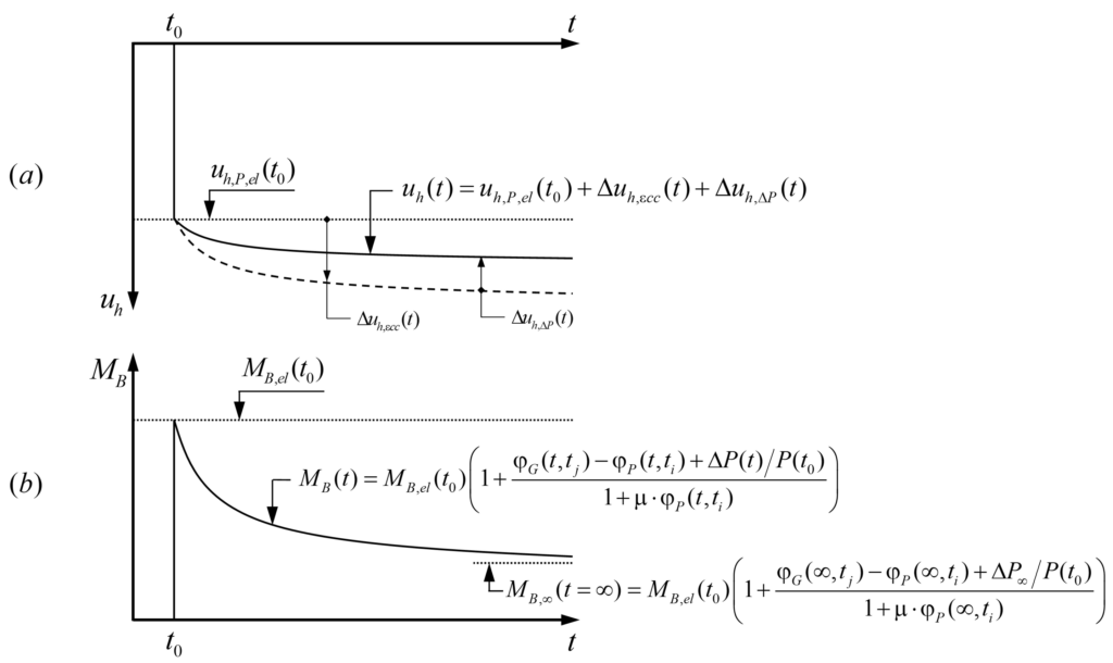
When the prestressing force is applied at the initial time (t=t0), the pier head exhibits an initial horizontal elastic displacement uh,P,el(t0). Subsequently, the horizontal displacement increases over time due to the creep of the girder Δuh,ecc(t), which is partly compensated by the prestressing force decrease due to the prestressing losses Δuh,ΔP(t), see Figure 6(a). On the other hand, the bending moment MB,el(t0) at the pier head caused by the imposed horizontal displacement uh,P,el(t0), elastic deformation of the girder caused by prestressing, is reduced over time due to creep and the prestressing losses ΔP(t) of the pier (Figure 6(b)). The bending moment MB(t) can be expressed as follows:
![\[{{M}_{B}}(t)={{M}_{B,el}}({{t}_{0}})+\Delta {{M}_{B}}(t)\text{ (eq}\text{. 12)}\]](https://concrete.ethz.ch/wp-content/ql-cache/quicklatex.com-55a97bd69ced108af2fd134b99e77193_l3.png "Rendered by QuickLaTeX.com")
Where ΔMB(t) is the bending moment increment over time due to creep of pier and girder, as well as the prestressing losses.
For calculating the bending moments MB(t) at the pier head over time, similar to calculations for shrinkage, we firstly apply the rotation compatibility at the initial time, and secondly, the time-dependent rotation compatibility using Trost’s method.
Rotation compatibility condition at the initial time t=t0:
Rotation compatibility in the basic system (BS) at the initial time (Figure 5) yields:

The initial bending moment MB(t0) at the pier head is equal to the initial elastic bending moment MB,el(t0), see eq. 14.
Time-dependent rotation compatibility condition (Trost’s method):
In the following, the equations are developed by using Trost’s method to determine the bending moment increment at the pier head over time ΔMB(t).
![\[{{\theta }_{B}}(t)={{\theta }_{B0}}\left[ 1+{{\varphi }_{P}}(t,{{t}_{i}}) \right]+{{M}_{B}}({{t}_{0}})\cdot {{\theta }_{B1}}\left[ 1+{{\varphi }_{P}}(t,{{t}_{i}}) \right]+\Delta {{M}_{B}}(t)\cdot {{\theta }_{B1}}\left[ 1+\mu \cdot {{\varphi }_{P}}(t,{{t}_{i}}) \right]={{\theta }_{BS,P,el}}({{t}_{0}})+\Delta {{\theta }_{BS,\varepsilon cc}}(t)+\Delta {{\theta }_{BS,\Delta P}}(t)\text{ (eq}\text{. 15)}\]](https://concrete.ethz.ch/wp-content/ql-cache/quicklatex.com-95e08604465bf578f7c2d9519c21a4f8_l3.png "Rendered by QuickLaTeX.com")
Note that the rotation at Support B θB(t) over time, analogous to the horizontal displacement, consists of:
![\[{{\theta }_{B}}(t)={{\theta }_{B,P,el}}({{t}_{0}})+\Delta {{\theta }_{B,\varepsilon cc}}(t)+\Delta {{\theta }_{B,\Delta P}}(t)\]](https://concrete.ethz.ch/wp-content/ql-cache/quicklatex.com-1ae664796905f139a2ab67077891e71c_l3.png "Rendered by QuickLaTeX.com")
where,

Substituting eq. 13 and eq. 14 in eq.15:
![\begin{align*} & {{\theta }_{B}}(t)={{M}_{B,el}}({{t}_{0}})\cdot {{\theta }_{B1}}\cdot {{\varphi }_{P}}(t,{{t}_{i}})+\Delta {{M}_{B}}(t)\cdot {{\theta }_{B1}}\left[ 1+\mu \cdot {{\varphi }_{P}}(t,{{t}_{i}}) \right]=\Delta {{\theta }_{BS,\varepsilon cc}}(t)+\Delta {{\theta }_{BS,\Delta P}}(t)\text{ (eq}\text{. 16)} \\ & \Delta {{M}_{B}}(t)=\left[ \frac{\Delta {{\theta }_{BS,\varepsilon cc}}(t)}{{{\theta }_{B1}}}+\frac{\Delta {{\theta }_{BS,\Delta P}}(t)}{{{\theta }_{B1}}}-{{M}_{B,el}}({{t}_{0}})\cdot {{\varphi }_{P}}(t,{{t}_{i}}) \right]\cdot \frac{1}{1+\mu \cdot {{\varphi }_{P}}(t,{{t}_{i}})}\text{ (eq}\text{. 17)} \\\end{align*}](https://concrete.ethz.ch/wp-content/ql-cache/quicklatex.com-7aebd9312fb06ce73977c40eccc9b7d6_l3.png "Rendered by QuickLaTeX.com")
On the other hand, the bending moment and the rotation at the pier head can be assumed to be proportional to the horizontal displacement over time. Therefore, from eq. 10 and eq. 11, we can formulate the bending moment increments ΔMB,εcc,el(t) and ΔMB,ΔP,el(t) due to creep and prestressing losses, respectively, as follows:

Substituting eq. 18 and eq. 19 in eq. 17:
![\[\Delta {{M}_{B}}(t)={{M}_{B,el}}({{t}_{0}})\cdot \frac{{{\varphi }_{G}}(t,{{t}_{j}})-{{\varphi }_{P}}(t,{{t}_{i}})+\frac{\Delta P(t)}{P({{t}_{0}})}}{1+\mu \cdot {{\varphi }_{P}}(t,{{t}_{i}})}\text{ (eq}\text{. 20)}\]](https://concrete.ethz.ch/wp-content/ql-cache/quicklatex.com-b75d1f9b09abd752031f43b8a4bcc97b_l3.png "Rendered by QuickLaTeX.com")
Finally, by substituting the bending moment increment ΔMB(t) from eq. 20 in eq. 12, the total bending moment at the pier head over time MB(t) is as follows:

3. Summary and discusion
Shrinkage:
The bending moment MB,∞ at the pier head at the infinite time due to shrinkage is as follows:
![\[{{M}_{B,\infty }}={{M}_{B,el,\infty }}\frac{1}{1+\mu \cdot {{\varphi }_{P}}(\infty ,{{t}_{i}})}\]](https://concrete.ethz.ch/wp-content/ql-cache/quicklatex.com-a37758496dd3dc3ef9adfe7890ce3986_l3.png "Rendered by QuickLaTeX.com")
Where μ ≈ 0.80 and ti, is the age of the pier concrete when the girder starts to shrink. Figure 7 shows the ratio of the bending moment MB,∞ to the elastic bending moment MB,el,∞ at the pier head at the infinite time as a function of the pier creep coefficient φP(∞,ti).
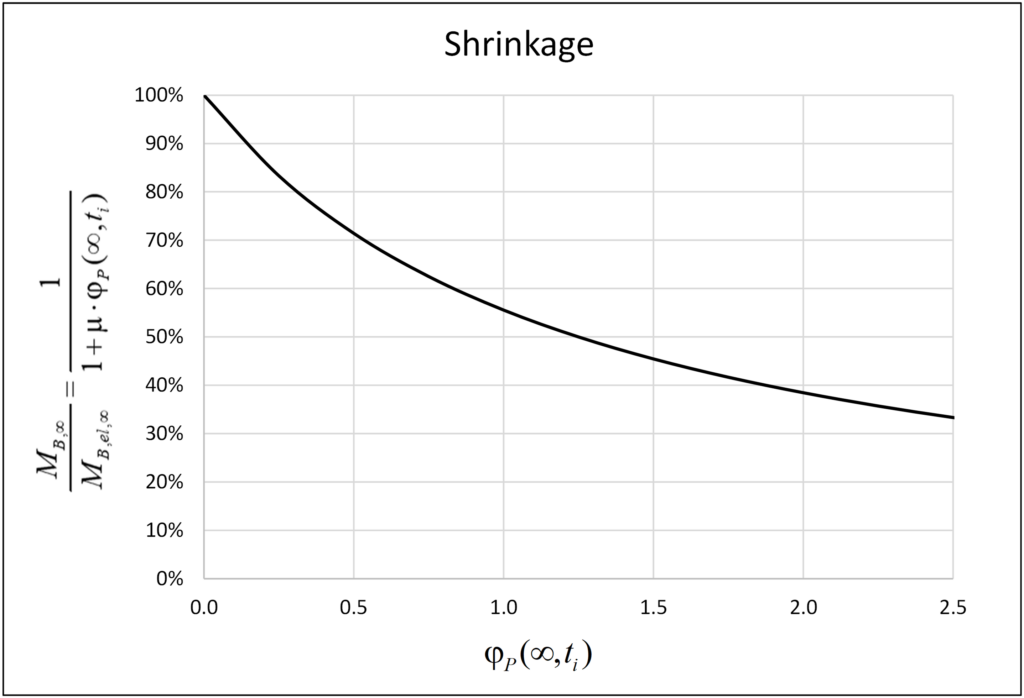
The bending moment MB(t) at the pier head due to shrinkage grows over time until it reaches a maximum bending moment MB,∞ at the infinite time (see Figure 4(b)), which is 1/(1+m·φjP(∞,ti)) times the elastic bending moment MB,el,∞ due to the short-term effect of the total shrinkage εcs,∞. The maximum bending moment MB,∞ at the pier head at the infinite time, which is independent of the girder creep coefficient φG(∞,ti), is equal to 38%·MB,el,∞ for a typical value of φP(∞,ti) = 2.0. This is the reason why many engineers consider 40% of the total shrinkage (40%·εcs,∞) to determine the internal forces in the piers at the infinite time due to long-term effects. However, since the piers are built ahead of the girder, the pier creep coefficient is often smaller than 2.0 at the concrete age when the girder starts to shrink, and anyway smaller in regions with high relative humidity (e.g. φP(∞,t0) ≈ 1.8 for C30/37 and RH ≈ 80% as common in Switzerland). Furthermore, if the beneficial effect of a cracked pier with correspondingly reduced stiffness is considered, an even lower equivalent creep coefficient jP (determined e.g. from a cross-sectional analysis, as the ratio of curvatures with and without creep) needs to be used. If the engineers do not have this background and use the reference of 40% (φP(∞,ti) = 2.0) indiscriminately, or even with a reduced value of shrinkage due to the high humidity, the design of the piers may be unsafe, particularly in SLS. For example, considering a pier creep coefficient at infinite time φP(∞,ti) = 1.25 from the time when the girder starts to shrink, the bending moment at the pier head is MB,∞ = 50%·MB,el,∞ , i.e. 32% higher than MB,∞ = 38%·MB,el,∞ for φP(∞,ti) = 2.0.
Prestressing:
The bending moment MB,∞ at the pier head at infinite time caused by prestressing (including short- and long-term effects) is:
![\[{{M}_{B,\infty }}={{M}_{B,el}}({{t}_{0}})\cdot \left( 1+\frac{{{\varphi }_{G}}(\infty ,{{t}_{j}})-{{\varphi }_{P}}(\infty ,{{t}_{i}})+\frac{\Delta {{P}_{\infty }}}{P({{t}_{0}})}}{1+\mu \cdot {{\varphi }_{P}}(\infty ,{{t}_{i}})} \right)\]](https://concrete.ethz.ch/wp-content/ql-cache/quicklatex.com-17534854d9d020a94b6d2381226cbdb9_l3.png "Rendered by QuickLaTeX.com")
where, tj and ti are the concrete age of the girder and pier, respectively, when the prestressing is applied.
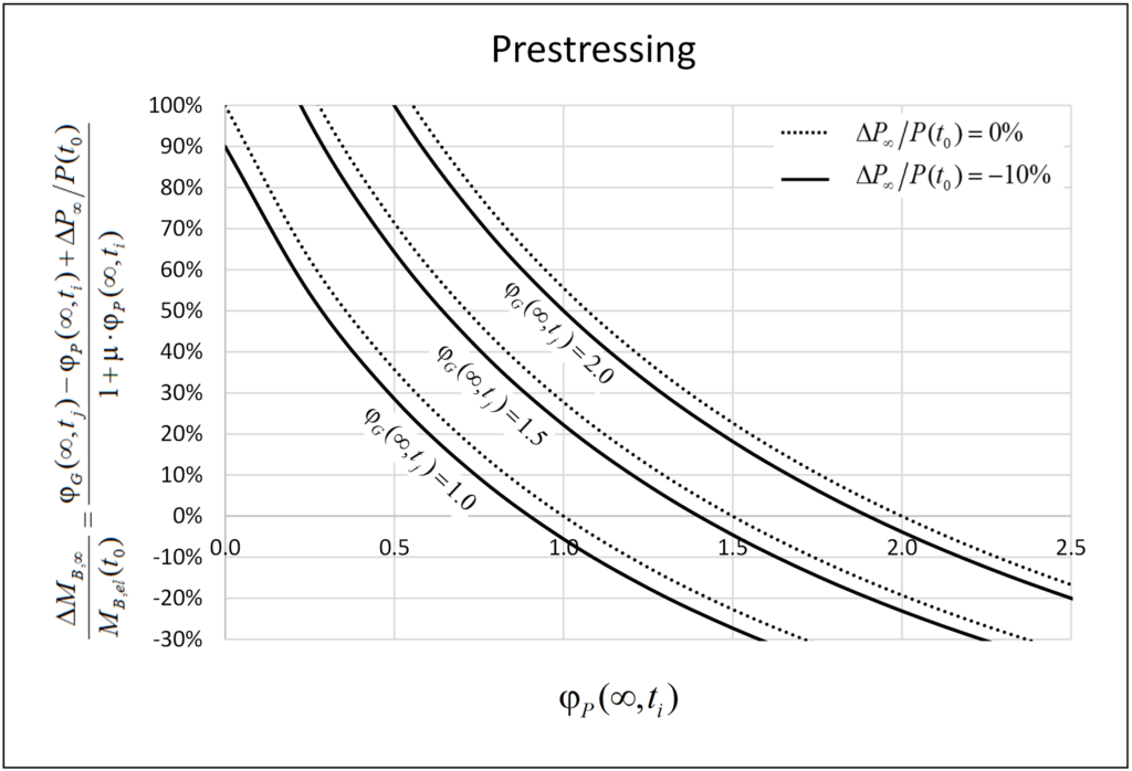
Figure 8 shows the ratio of the bending moment increment ΔMB,∞ to the initial elastic bending moment MB,el(t0) at the pier head at the infinite time. Indeed, as often assumed in design, creep of the pier, together with the (negative) contribution of the prestressing losses, counteract and for specific values of the creep coefficients even compensate the increase of the pier head bending moments caused by creep of the girder. However, in typical cases, significant differences are observed. Generally, the ratio ΔMB,∞ / MB,el(t0) is a function of the pier creep coefficient φP(∞,ti), the girder creep coefficient φG(∞,tj), the prestressing losses ΔP∞/P(t0) and the coefficient m. The curves plotted in Figure 8 have been generated for μ=0.80, φG(∞,tj) = {1.0; 1.5; 2.0} and ΔP∞/P(t0)= {0%; 10%}. It is observed that the prestressing losses have a minor effect on the ratio ΔMB,∞ / MB,el(t0) (around 5% for the parameters used), which could be neglected in the calculations.
The ratio ΔMB,∞ / MB,el(t0) depends on the girder and pier creep coefficients (with ti and tj = concrete age of these elements when the prestressing is applied), and the prestressing losses. The initial bending moment MB,el(t0) at the pier head decreases over time if the pier creep coefficient φP(∞,ti) is higher than the girder creep coefficient φG(∞,tj), i.e. φP(∞,ti) > φG(∞,tj), but increases otherwise (neglecting prestressing losses), which typically applies since the piers are built ahead of the girder.
Considering a pier creep coefficient of φP(∞,ti) = 1.25, the bending moment increment ΔMB,∞ at infinite time increases by roughly 10% and 35% to the initial bending moment MB,el(t0) for girder creep coefficients of φG(∞,tj) = 1.5 and φG(∞,tj) = 2.0, respectively. An increase of 35% is not a priori negligible; however, it can be neglected for low and moderate prestressing levels of the girder since the bending moment increment ΔMB,∞ is usually small compared to the bending moment caused by shrinkage.
4. Conclusions
For a preliminary design (internal action estimation) of piers monolithically connected to a prestressed girder, it is a valid approximation to consider 40…50% of the total shrinkage at the infinite time εcs,∞ and neglect the incremental internal force over time due to prestressing. These considerations may also be acceptable in detailed design if the dimensioning of the piers is not decisive and the designer has control over the influence of the long-term effects on the structure, including its construction process. Generally, however, using a value of 40%·εcs,∞ indiscriminately to take into account the long-term effects may be unsafe side by underestimating the internal forces acting in the piers.
The equations presented for estimating the internal forces in the piers due to the long-term effects are useful in engineering practice. They allow a simple, yet considerably more accurate long-term analysis as required for long jointless structures with monolithic pier-girder connections. In addition, a proper strategy of casting stages can significantly help increase the lengths of jointless structures.
As a final remark, it is noted that while the moments at the pier heads caused by shrinkage and prestressing are reduced due to creep of the piers, the full girder displacements need to be accounted for when designing bearings and expansion joints and estimating bridge end displacements in integral abutments.
I hope this publication has been of interest and useful to you. Leave your comments.
Alejandro Giraldo Soto
Kommentieren Sie diesen Beitrag auf LinkedIn oder Instagram