Link zur deutschen Version: Ein neuer Ansatz für Schalenelemente in der Finiten Elemente Analyse
In this blog post, I will focus on demonstrating the development of a novel so-called “hybrid machine-learning – finite element analysis” (hybrid ML-FEA) framework for shell elements. More specifically, I will focus on the data used to create this framework. In my last blog post, I have already elaborated on the motivation for using machine learning within the finite element analysis for reinforced concrete (RC) structures and shown a simple example of a surrogate model on a RC beam. In short: A neural network was trained to overcome the iterative task of determining the curvature based on the moment at any cross-section of a potentially cracked RC beam.
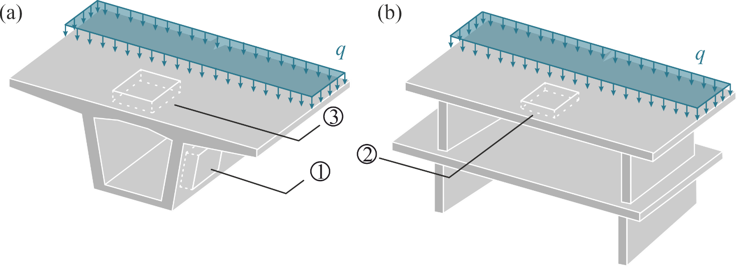
However, RC plates and shells (as opposed to RC beams) are often used in construction as fundamental components of large civil structures. Figure 1 shows three typical examples of RC shell elements in a bridge girder’s web or deck ((a), No. 1 and 3) or a standard ceiling slab ((b), No. 2). It is therefore important to investigate the usefulness of machine learning in a shell-element-based FEA to create a meaningful hybrid ML-FEA framework for RC structures that can be used to surrogate (or substitute) the standard FEA.
Compared to other machine-learning based surrogate models, this framework differs in the level on which it is applied within the FEA. Where other methods (e.g. Kuhn et al., see separate Blogpost) replace the entire FEA or try to find new material models by surrogating the stress ( ) – strain (
 ) relationship on a material point (e.g. Neural Metamaterial Networks by Li et al.), the hybrid ML-FEA framework developed here shall be applicable on the finite element level, meaning on the level of one shell element.
This implies that the ML model will surrogate the relationship between generalised stresses ( ) and generalised strains (
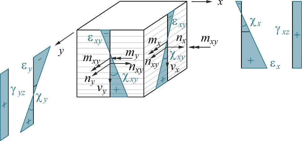
 ). These each comprise eight variables as shown below for a layered shell finite element used to model RC (Figure 2 and Equation 1): Three membrane force resp. strain components (
 resp.
resp.  ), three moment resp. curvature components (
 resp.
resp.  ) and two shear force resp. strain components: (
 resp.
resp.  ). In Equation 1,
  represents the generalised stiffness matrix, which relates the generalised strains to the generalised stresses.
![\[\left\{\begin{matrix} n_x, n_y, n_{xy} \\ m_x, m_y, m_{xy} \\ v_{xz}, v_{yz}\end{matrix} \right\} = \left[\mathbf{D}\right]\left\{ \begin{matrix} \varepsilon_x, \varepsilon_y, \varepsilon_{xy} \\ \chi_x, \chi_y, \chi_{xy} \\ \gamma_{xz}, \gamma_{yz}\end{matrix}\right\}\]](https://concrete.ethz.ch/wp-content/ql-cache/quicklatex.com-d5d52354e3fa2da1d0d41ff7897df52f_l3.png "Rendered by QuickLaTeX.com")
Equation 1: Relationship between generalised stresses and strains.
In a first instance of investigating the hybrid ML-FEA framework for linear elastic layered shell elements based on the Reissner-Mindlin plate theory are analysed (Figure 2, Equation 1). Compared to the standard Kirchhoff plate elements, the Reissner-Mindlin shell elements also include out-of-plane shear components and are used for thick shell elements (Equation 1). Additionally, the layers of the shell element, modelled in plane stress, allow for analysing the strain and stress states of the individual layers separately. Hence, during the FEA, first the strain states and second the stress states are evaluated in every layer, the latter of which are then integrated across the height of the element to determine the generalised stresses (). The linear elasticity simplifies the problem for the first step of this investigation and results in a closed formulation for the matrix (i.e. can be calculated analytically). For a more complex material behaviour such as for nonlinear RC, this matrix is not available in closed form and needs to be determined iteratively. The matrix then depends on the different strain states of the layers in the shell element and, hence, on the applied material models (i.e. the material models applied in the cracked membrane model Usermat).
At this point, it is important to note that the linear elastic framework is simplified to such a big extent that a machine learning algorithm can neither improve the speed nor the accuracy of the problem. The reason for still implementing the hybrid ML-FEA framework for this case is purely to understand its application in a case where the standard FEA can easily be applied due to the analytical solution. The future goal is to extend this framework to more complex layered shell elements such as the ones used for the nonlinear analysis of RC shells.
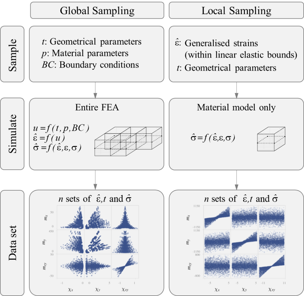
To create the ML model, we need two main components: Data and a suitable ML architecture. For this blog post, I would like to focus on the data acquisition. In this example, the data is generated from the standard FEA simulation. The simulation takes quite some time, however once the data is gathered, a request to the ML-FEA hybrid framework will be at least as fast as the standard calculation (i.e. in this case the analytical equation). There are two different ways in which the data can be generated from the FEA simulation: Global sampling and local sampling (Figure 3). In the global case, different plate characteristics and boundary conditions are chosen with a Latin Hypercube Sampler (see also Wikipedia) and then simulated with a standard FEA. On the other hand, in the local sampling, the generalised strains are sampled directly with the Latin Hypercube Sampler. These then only need to be passed through the material model instead of the entire FEA to create the desired data. The final data set then consists of n sets of ,  ,
,  and . Even though these two sampling methods seem as though they should lead to similar datasets, the choice of the sampling strategy turned out to be a pivotal decision for the trainability of the ML model. As you can see in Figure 3, the data generated with local sampling leads to a much more evenly distributed data set, which leads to an increased accuracy in the predicted generalised stresses. This means that the ML model can be trained better and shows that every model is only as good as its underlying data.
 : Displacements;
  : a function).
You might be wondering why I did not use experimental data for this investigation, but instead had to first sample the data from the linear elastic material model. The reason for this is twofold: First, this example is very preliminary and used only for linear elastic cases, which would be difficult to extract from experimental data and also wouldn’t reflect the entire behaviour of a test specimen, i.e. only the uncracked part. Second, experimental data is scarce, particularly experimental data with known generalised strain and stress states. Currently, as a next part of the project, experimental data from shell element tests (e.g. from LUSET experiments) are gathered to try and create a data set for the nonlinear analysis of RC. However, chances are, that this data set does not comprise a distribution suitable for training a ML model on it.
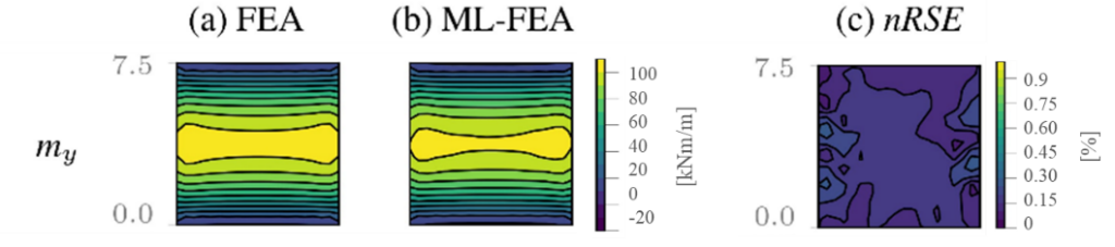
After sampling the data from the linear elastic material model, different physics-based ML models were tested to keep the mechanical relationship  encoded in the ML architecture. A training with a Deep Operator Network yielded the most accurate test predictions and was therefore used for the linear elastic hybrid ML-FEA framework. More detailed explanations about the chosen architectures can be found in the paper [1]. This Deep Operator Network was then used in an example finite element calculation shown in Figure 4: A ceiling slab exposed to bending in one direction (Location 2 in Figure 1), consisting of 100 shell finite elements (10×10). Figure 4 outlines that the standard FEA (a) and the ML-FEA hybrid framework (b), in which each shell element is surrogated with the ML model, yielded very similar results, which is also underlined by the error calculation of a normalised root squared error (nRSE) (c). With this example, the application of a ML-FEA hybrid framework in the simplified linear elastic case was shown to be feasible.
A paper was submitted to the fib Symposium taking place in June 2025. This paper will be made available within this blog post as soon as it is published online – until then, feel free to reach out to me, I’d be happy to explain more. Stay tuned for the next findings in machine learning for finite element analyses of reinforced concrete structures!
Vera Balmer
Literatur