Link zur deutschen Version: Lokale Korrosion der Bewehrung – kleiner Schaden mit grosser Tragweite
The reinforcement of many ageing reinforced concrete structures is corroding. The reasons for this are manifold and range from the carbonation of the concrete and the ingress of chlorides to a concrete cover with high permeability. There is a considerable damage potential, especially in the case of pitting corrosion, due to the very high corrosion rate as a consequence of macro-element formation (the cross-section loss is typically in the range of 1 mm per year). But what are the effects of localised corrosion on the load-bearing and deformation capacity of affected structures? That is what this blog post is about.
Hidden damage – huge uncertainty
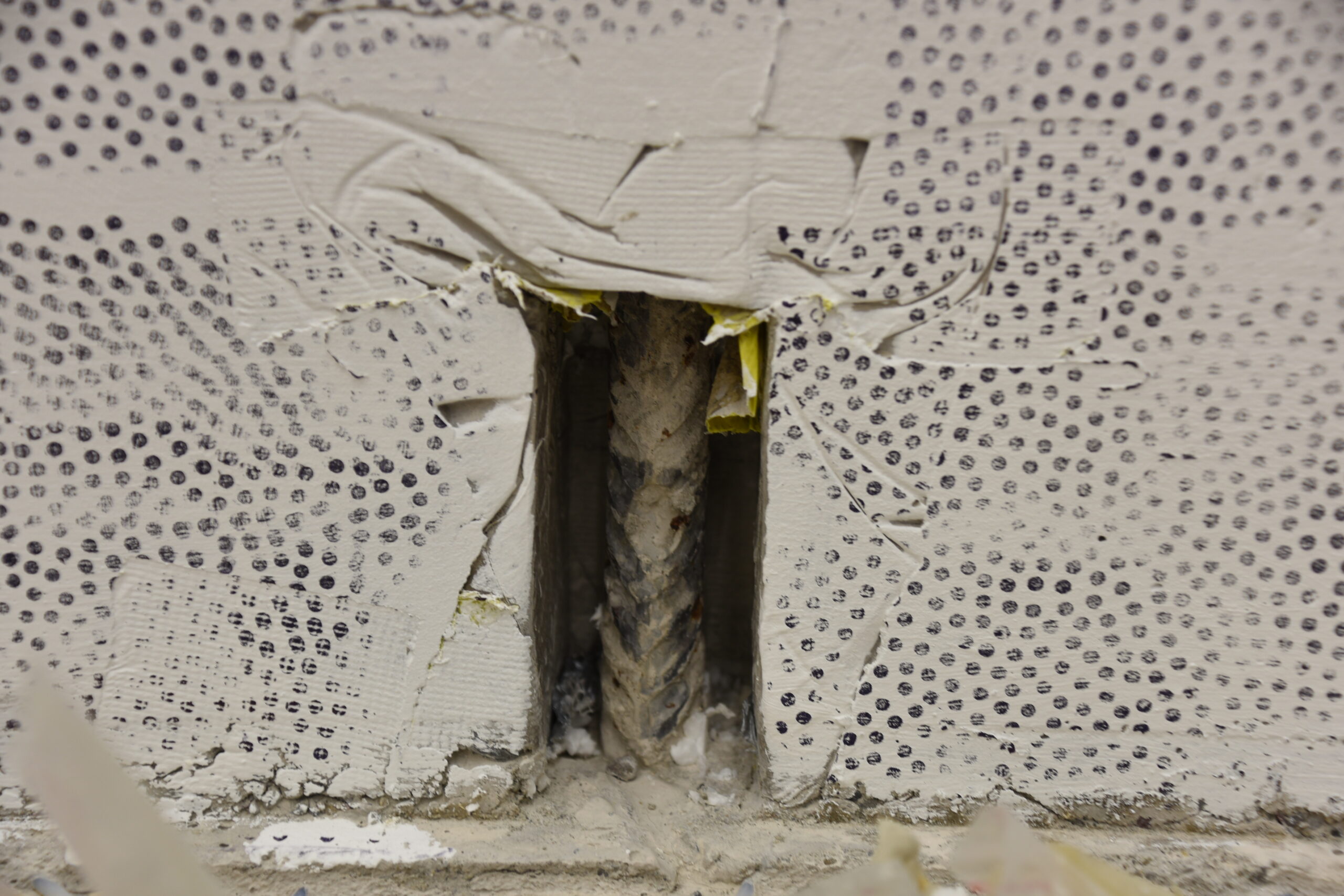
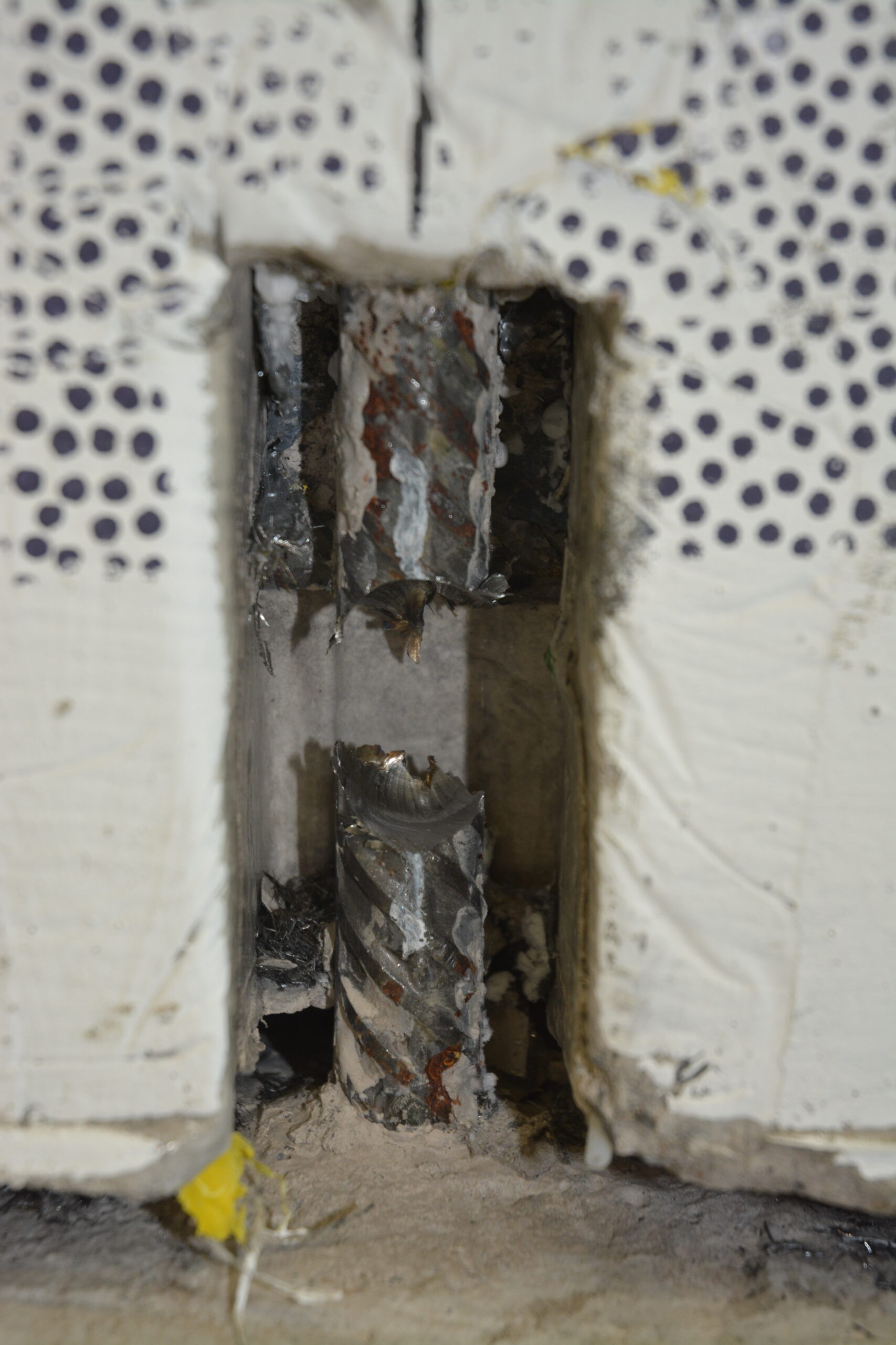
A pilot study conducted by the Federal Roads Office (FEDRO) revealed that many cantilever retaining walls along the motorways built in the 1960s and 1970s are corroding. On average, about 36% of the examined reinforcing bars showed corrosion damage, and the mean cross-section loss of the affected bars was 25%. Affected is the flexural reinforcement on the side facing the ground above the construction joint between footing and wall. The local corrosion is highly probable to be caused by honeycombs, i.e. a highly permeable concrete cover, resulting from improper casting and compaction of the concrete, without any chloride ingress.
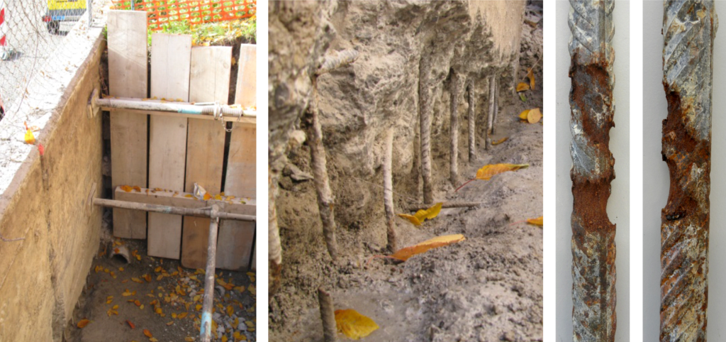
In the pilot study, corrosion detection proved to be extremely difficult for such structures. The thickness of the walls above the footing impeded any reliable statement on the reinforcement’s condition at the opposite side using standard measuring techniques. Only visual inspection revealed the extent of corrosion damage, which required building shafts behind the wall and removing the (damaged) concrete cover.
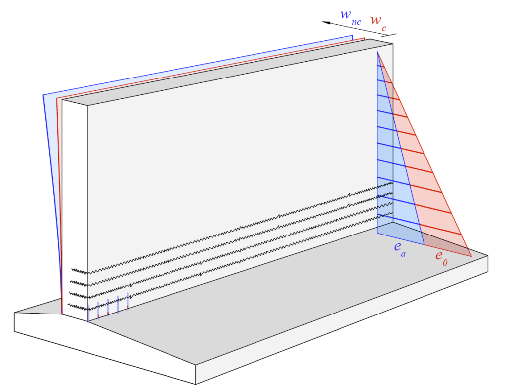
The uncertainty regarding the number of affected structures and their load-bearing behaviour impelled FEDRO to launch five research projects together with the Federal Office of Transport (FOT; the railways also have many retaining walls). We are pleased to work on one of them. The project investigates the load-bearing behaviour and deformation capacity of cantilever retaining walls with locally corroding reinforcement. An initial analysis at the beginning of the project indicated that the load-bearing capacity of these structures is likely to be disproportionately reduced (i.e. the residual capacity would be overestimated if only the loss of cross-section was considered). In addition, the deformation capacity is drastically reduced due to the localised damage. The latter is particularly relevant as these walls were initially designed to resist active earth pressures, which was in accordance with the code provisions at that time. This approach presumes a deflection of the wall and therefore a sufficient deformation capacity at the ultimate limit state. If the deformation capacity is reduced, an increased earth pressure action has to be considered (in extreme cases even earth pressure at rest) in addition to the reduced load-bearing capacity. This combination is an uncomfortable starting point for any assessment.
Local corrosion – diverse effects
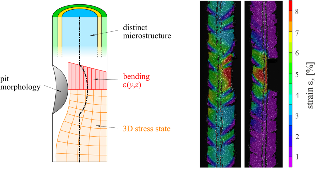
It is widely recognised among the research community that the damage geometry (i.e. pit morphology) decisively influences a reinforcing bar’s behaviour in the vicinity of the pit. Due to the cross-section reduction, stress trajectories converge and an inhomogeneous, three-dimensional stress state occurs over the cross-section. The constitutive relationships, determined from tension tests on the undamaged reinforcing bar, are no longer valid.
Additionally, local bending moments occur due to a shift of the neutral axis in case of unilateral corrosion damage. Unilateral damage is often observed for pitting corrosion and the corresponding bending moments have to be superimposed to the tensile force. Although bending moments decrease as soon as the reinforcing bar yields (and a local plastic hinge is formed), ultimate strains are reached much earlier due to the large curvature. This may lead to a premature failure, as experimental results of this project indicated.
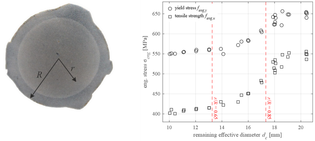
Since the late 1970s, the majority of reinforcing steel worldwide is produced using a process called “quenching and self-tempering” (QST, brand name “Tempcore”), so also in Europe. Due to this production process, these bars consist of three distinct material layers over their cross-section, which exhibit different material characteristics. Consequently, if a QST reinforcing bar corrodes, its mechanical characteristics are continuously altered with a progressing loss of cross-section. Especially, its tensile strength is reduced, as the innermost layer has an almost 30% lower tensile strength compared to the outer annulus.
A short damage length proves to be highly unfavourable for a reinforcing bar’s deformation capacity. The bar deforms almost only in the damaged section, and strain localisation occurs. The critical point is reached if the ultimate force of the damaged section is not sufficient to yield the adjacent undamaged parts of the reinforcing bar. Thus, the bar almost lost its entire plastic deformation capacity. Considering today’s reinforcing bars produced in Europe, this is the case for comparably low cross-section losses between 12% and 20% (note that the mean cross-section loss reported in the pilot study of FEDRO was 25%). To make matters worse, the critical section for retaining walls lays just next to a lap splice (reinforcing bars are traditionally spliced above the construction joint), where a structure’s deformation capacity is reduced anyway, as a new yet unpublished study shows.
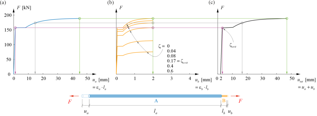
Example of a load-deformation curve of a reinforcing bar. Left: for the undamaged section A (blue); centre: for the damaged section B (orange); right: for the entire bar A+B. ζ = loss of cross-sectional area (between 0 (no loss) and 1 (bar is fully corroded)). The loss of deformation capacity is visible for a short damage length lb<<la and ζ between 0 (green) and 0.17 (pink).
Research on a small scale – and on a large scale
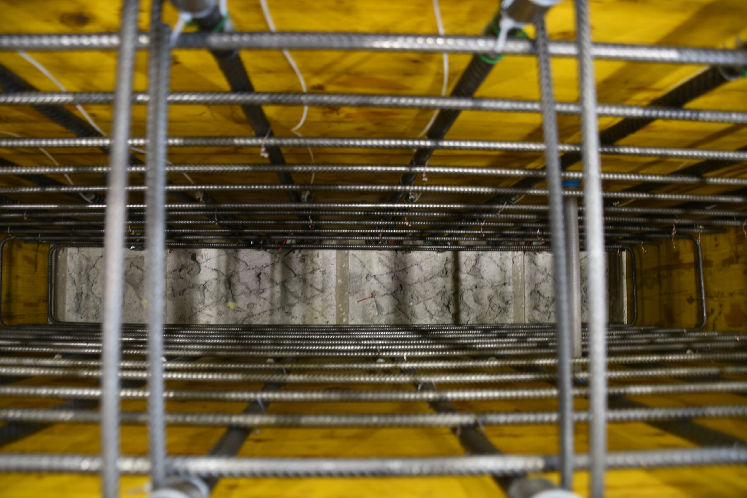
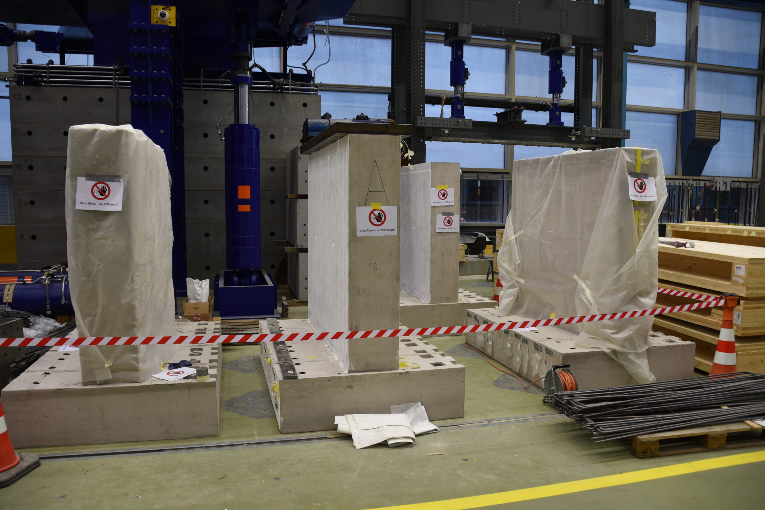
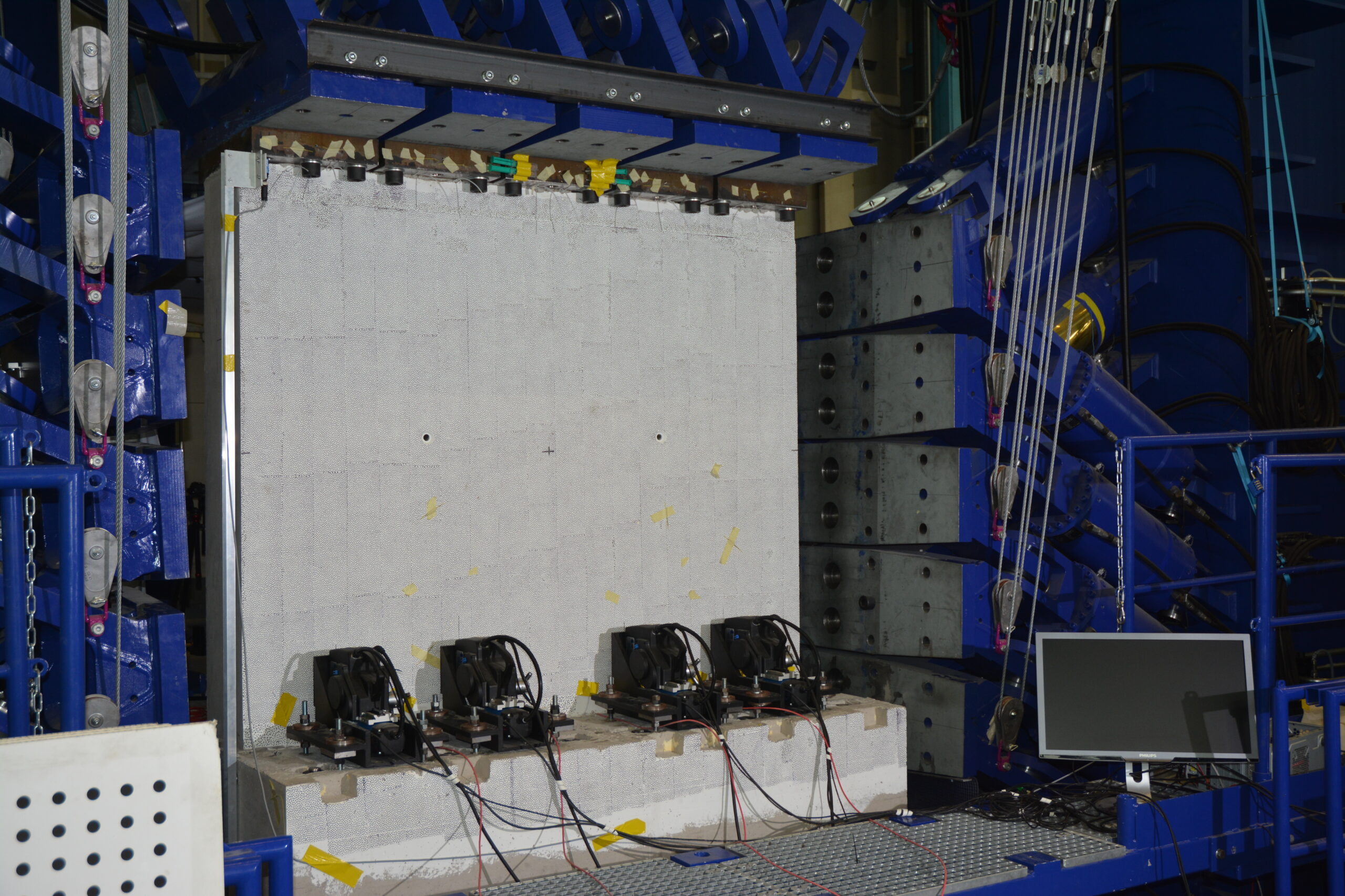
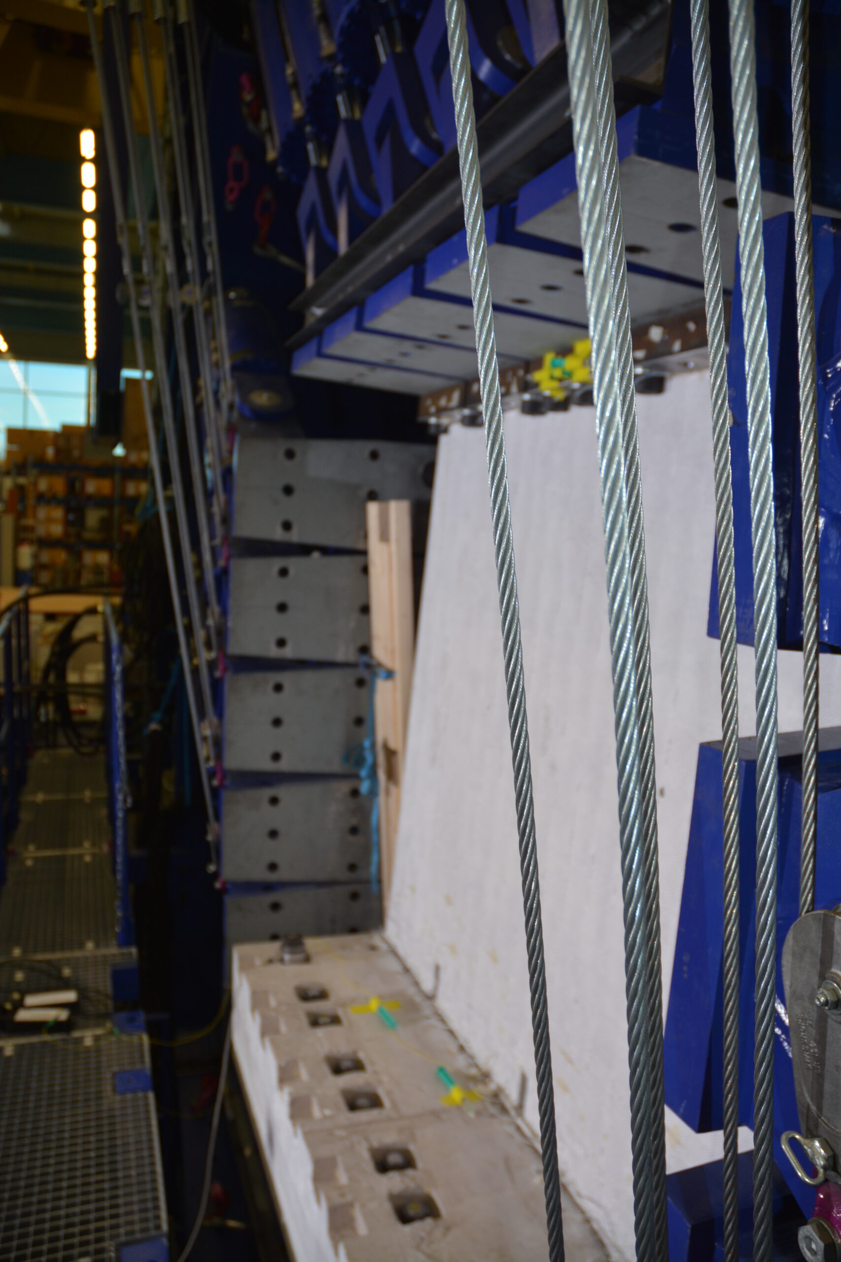
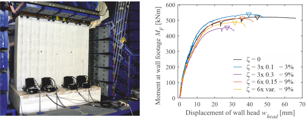
Besides more than 100 tensile tests on reinforcing bars containing various damage geometries, eight large-scale experiments on retaining wall sections were conducted in the Large Universal Shell Element Tester (LUSET) throughout this research project. The walls had a width of 2.0 m, a height of 1.7 m, and a thickness of 0.38 m. They were built on footings measuring 2.1 x 0.4 x 1.4 m. The elements weighed more than six tons and represented the lower part of a 4.7 m tall retaining wall. According to this height, the load was introduced at the element’s head in LUSET as a combination of normal force, shear force and bending moment.
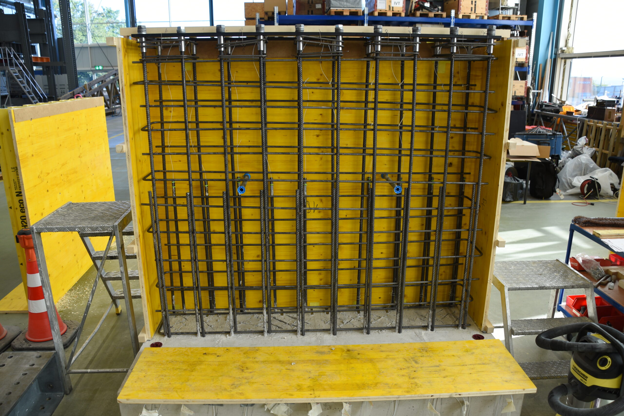
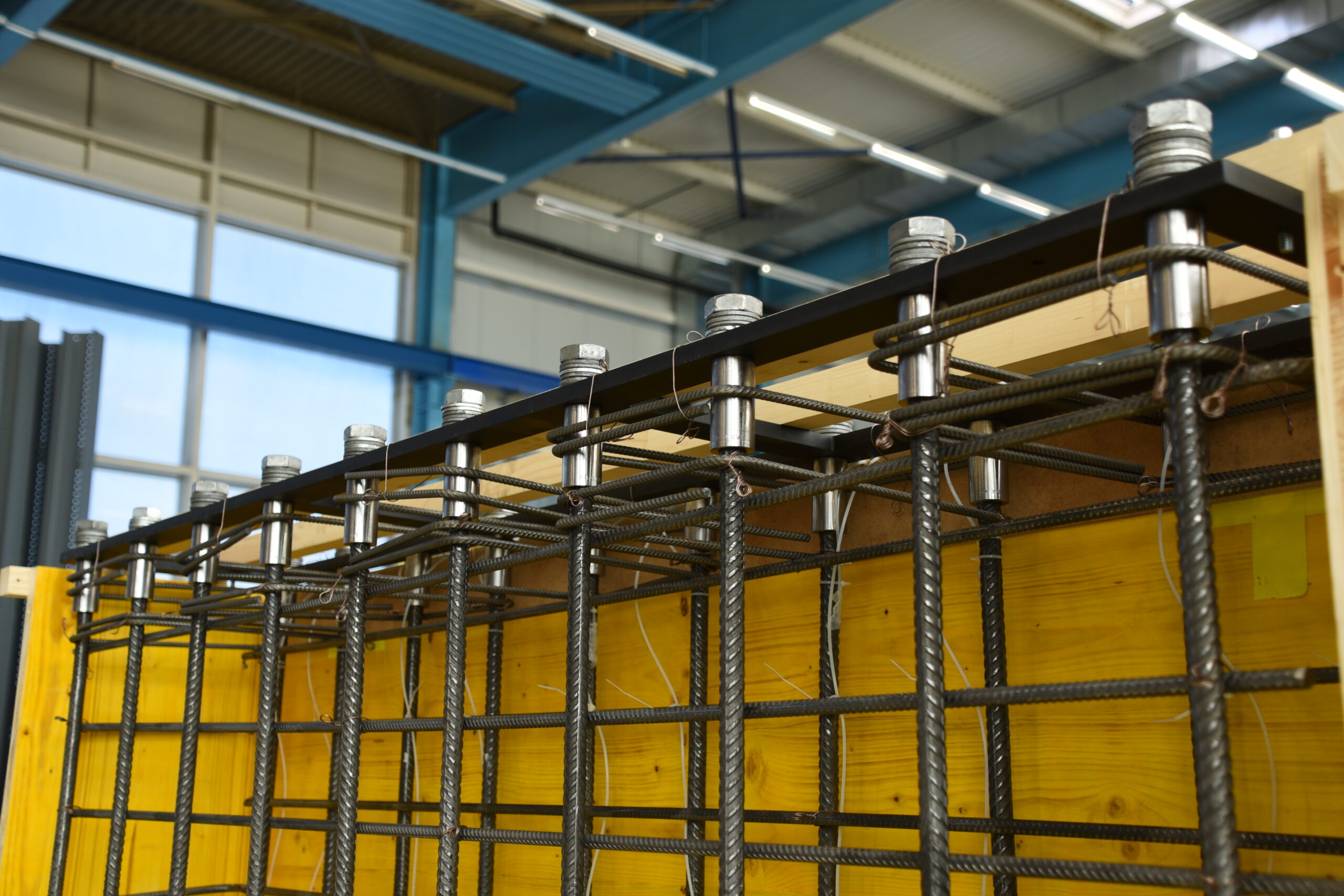

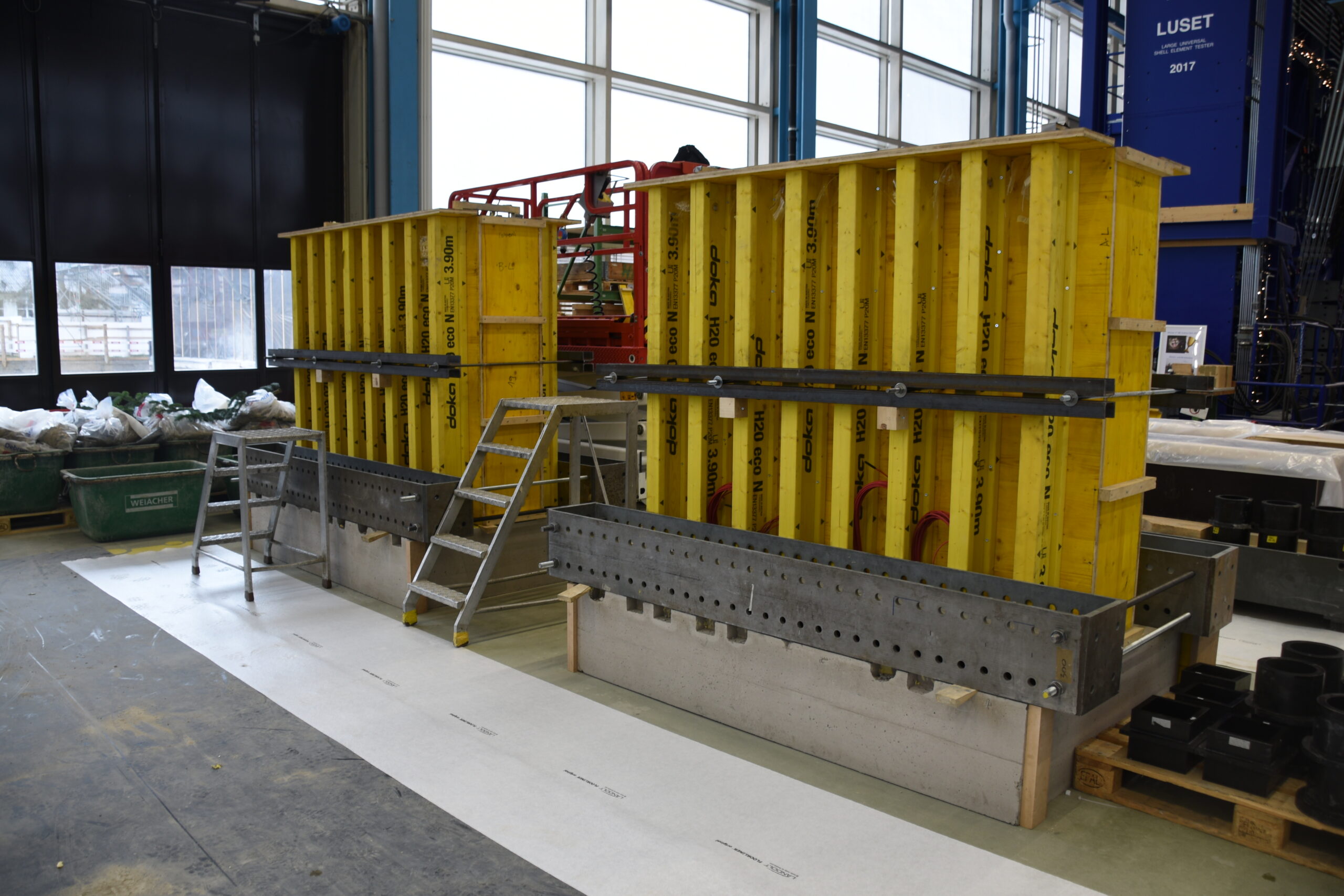
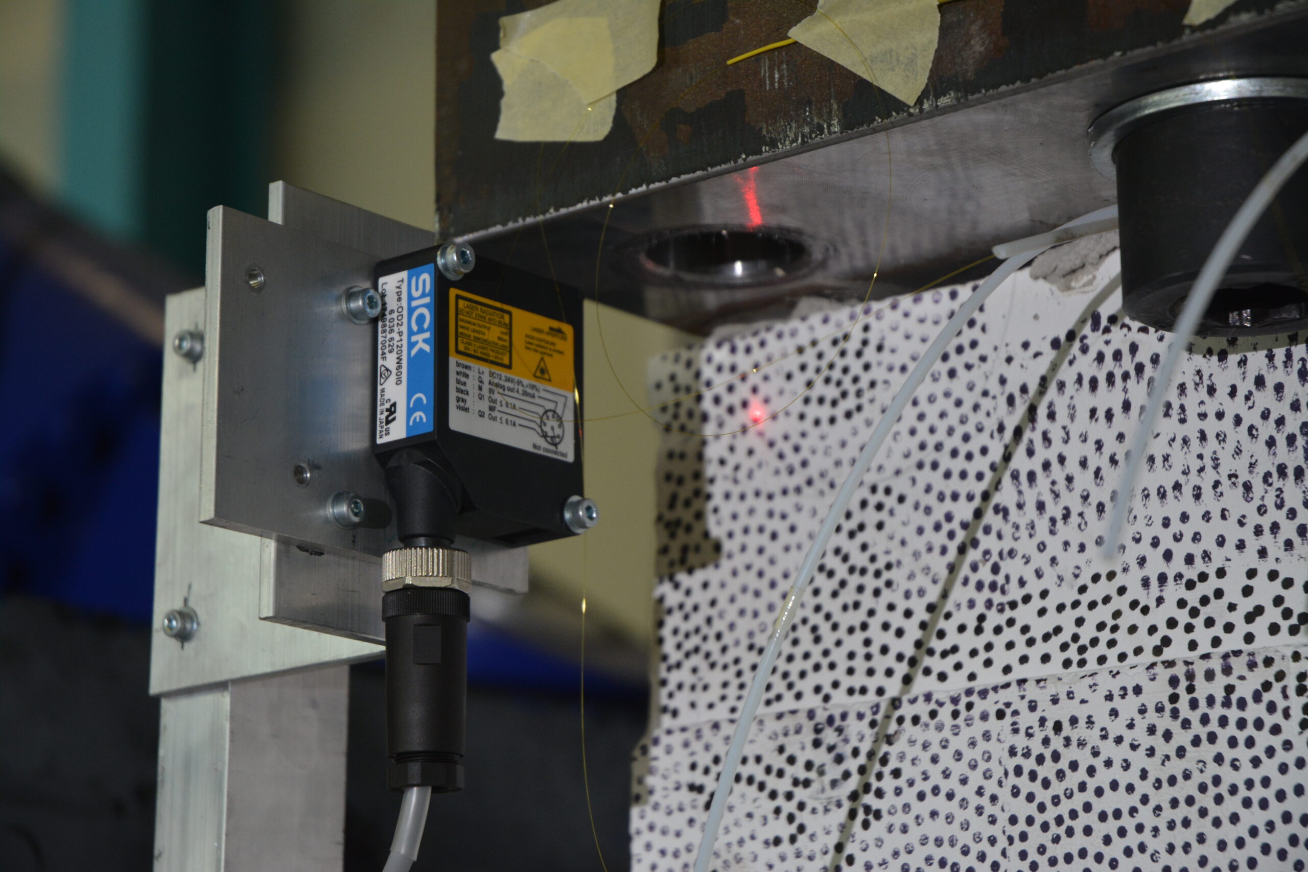
The specimens were instrumented using cutting-edge measurement technologies. Stresses in the reinforcing bars were calculated using fibre optic strain sensing with a few millimetres’ spatial resolution. The wall’s deformation and the kinematics of the formed cracks were measured with a three-dimensional digital image correlation system (DIC) with an accuracy in the range of hundredths of a millimetre.
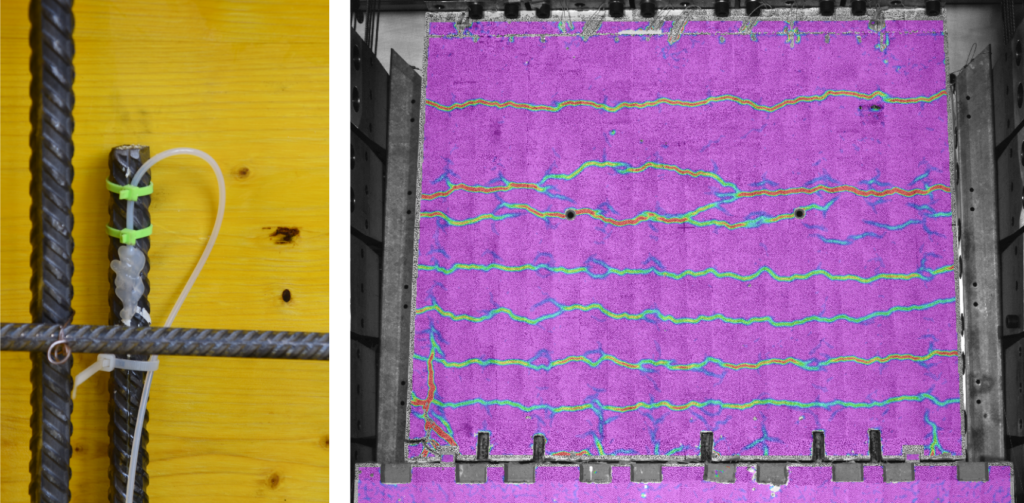
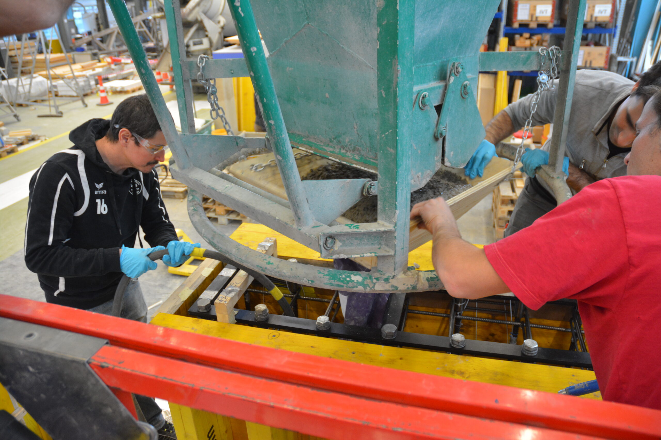
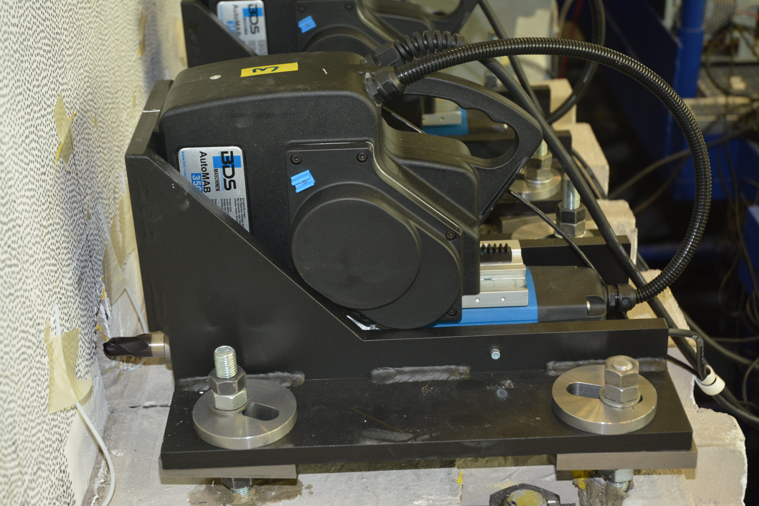
To investigate the influence of cross-section loss due to corrosion, some of the reinforcing bars were intentionally damaged prior to the experiments using a 20 mm diameter spherical mill. This type of “artificial corrosion” causes practically the same effects as “natural corrosion” induced electrochemically, as was shown by preliminary tests in collaboration with Prof. Dr. Ueli Angst. In three hybrid tests, four (of 10) reinforcing bars were damaged stepwise during the experiment using fully automatic drilling machines, which were installed at the footing of the wall. The applied load was continuously updated using the actual displacement of the wall’s head and a model provided by the Chair of Geomechanics (Prof. Dr. Alexander Puzrin, David Perozzi), which is capable of simulating the acting earth pressure as a function of the wall deflection. This ensured a realistic loading of the specimens.


What was found out up to now – and what is still to be investigated in the future
The load-bearing capacity of structural elements affected by local reinforcement corrosion is reduced disproportionally due to local phenomena in the vicinity of the corrosion pit. Models only considering the loss of cross-sectional area therefore overestimate the actual residual load-bearing capacity.
Local damage of the reinforcing bars leads to a substantial reduction (up to 85%) of an element’s deformation capacity, even for low cross-section losses. Hence, all models based on the lower bound theorem of plasticity theory – which most models in the codes are – are no longer valid without restrictions. Therefore, the actual deformation capacity of a structure needs to be assessed in detail.
The results of the conducted experiments on reinforcing bars and retaining wall sections prove the statements made above convincingly. The models developed in this research project are based on an extension of the established Tension Chord Model and are very promising to describe the load-deformation behaviour of structural elements affected by local corrosion. They can be used to assess cantilever retaining walls and other structural elements, whose deformation capacity is decisive (e.g. section over interior supports for continuous bridge girders).
One of the aims of this project is to formulate a (simplified) assessment guideline for practitioners. It is still discussed how these research results can be used by engineers in charge of assessing structures with localised corrosion. The discussion focuses on the consequences of the challenging corrosion detection and if and how the observation method can be used to further operate corroding retaining walls safely.
Whether filigree retaining walls are “passé”, as it was the title of an interview in Tec21 (40/2016), is finally a decision of the owner of these structures. The exposure is generally moderate (in contact with the ground, semi-humid, without chlorides). Therefore, such structures are not more vulnerable for corrosion than other structures under the same conditions, provided the use of state-of-the-art construction methods (meaning the use of a so-called “kicker formwork”, thorough compaction of the concrete, and covering the construction joint if needed). However, a general change of paradigm to massive heavyweight retaining walls, accompanied by a comparatively high use of resources and greenhouse gas emissions, is not indicated from our point of view.
Severin Haefliger