Link zur deutschen Version: Die Finite-Elemente-Methode im konstruktiven Ingenieurbau
Basic principles and areas of application of the FEM
In the last decades, computer-aided calculation methods – particularly the Finite-Element-Method (FEM) – have become an indispensable tool in engineering. With the development of the FEM, everyday calculations and routine tasks can be automated and carried out without careless mistakes. Thus (at least a part) of Konrad Zuse’s [1] dream of taking over “annoying” tasks by a fully automated calculating machine has become a reality. The engineer’s task has shifted from calculation to modelling and the interpretation of results, for which, however, the underlying theories and methods should be applied consciously and correctly. This has not made the art of structural analysis superfluous, but it has made it more demanding and exciting.
In general, the FEM provides a numerical approximation for all tasks that can be represented mathematically with partial differential equations, for which no closed solutions are available. More simply, complex systems (load-bearing structures) are divided into components (finite elements) and mathematically linked to form an overall model. If the mechanical properties (stiffness) of the individual elements are known through a relationship between stresses and strains specified within the framework of the selected mechanical model, the effects (e.g. internal forces) on the overall model can be determined under the given actions together with the boundary conditions (support conditions).
For the everyday tasks of a structural engineer, the linear-elastic FEM is mostly used, whereby a linear relationship between the stresses and strains is assumed. The FEM supplies e.g. the internal forces for the dimensioning of structures using ideal-plastic models. In exceptional cases, e.g. for the static verification of existing structures, the nonlinear [2] FEM is used more and more often. A nonlinear relationship between the stresses and strains is then applied, which allows the analysis of the load-deformation behaviour, the cracking behaviour and the associated redistribution of internal forces. In contrast to conventional calculation methods, this allows to identify load-bearing reserves, with which more efficient and resource-saving structures can be built or, ideally, expensive strengthenings can be avoided during a static verification of existing structures. While the pure application of such nonlinear FEM programs is relatively easy nowadays, thanks to user-friendly interfaces, choosing the appropriate (nonlinear) material and structural model for a given problem becomes more complex. The model ideas and their limitations, as well as the peculiarities of an NLFE calculation (e.g. divergences) should be understood in detail. Imparting this knowledge is a central challenge for us as a teaching and research institute.
Historical outline of the FEM
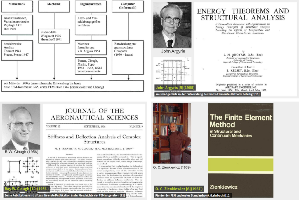
In general, the development of FEM does not go back to a single person or a single field but has a strong interdisciplinary character with aspects from mathematics, mechanics, engineering and computer science. The development of the FEM began in the 1950s and was pioneered by J. Argyris at the Technical University of Stuttgart, R.L. Taylor or R. Clough at the University of California, Berkely and O.C. Zienkiewicz at the University of Wales (all qualified civil engineers!). From the 1960s, the development picked up speed with the first international FEM conference in 1965 and the first standard book by Zienkiewicz in 1967 entitled “The Finite Element Method in Structural and Continuum Mechanics”.
The application of the FEM to reinforced concrete structures began in the late 1960s with the work of Ngeo and Scordelis 1967 and Rashid 1968. Since then, countless publications and books have been published with the theoretical basics, use cases and guidelines (see FIB bulletin 45 2008). The first FEM-software were developed at universities and developed into commercial FEM packages with increased user-friendliness after 1970. This resulted in a large number of different software, including different types of elements and various mathematical solution algorithms for the spatial and temporal discretisation of the given problem. D. Mitchel, M.P. Collins and F.J. Vecchio from the University of Toronto played a pioneering role in developing nonlinear material models for reinforced concrete in the 1980s (development of compression field theories and their implementation in the FEM-software VecTor). Today, the FEM is one of the most widely used numerical solution methods for various physical tasks in all engineering sciences up to weather forecasts. We can be all the more proud that civil engineers made a significant contribution to the development of the FEM.
NLFE-tools at the Chair of Concrete Structures and Bridge Design
At the Chair of Concrete Structures and Bridge Design, we concentrate on developing nonlinear material models and their implementation in numerical methods, such as FEM. In recent years, various tools for nonlinear finite element analysis of reinforced concrete and masonry structures have been developed:
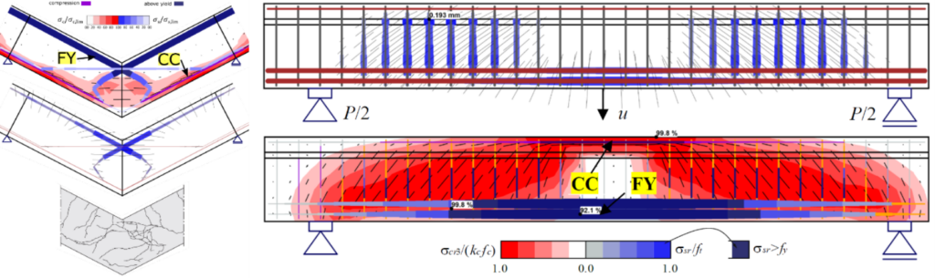
The Compatible Stress Field Method (CSFM) is suitable for analysing reinforced concrete under a plane stress state (e.g. frame corners or longitudinal beams of a box girder bridge, as shown in Figure 3). The CSFM is based mainly on the implementation of the tension chord model in the FEM-software Idea StatiCa Detail.
The CMM-Usermat contains the implementation of the Cracked Membrane Model (developed by Prof. Dr. Walter Kaufmann) as a user-defined material (Usermat) in the FEM program Ansys Mechanical APDL. Combined with a layer model, shell structures made of reinforced concrete can be analysed (see Figure 4).
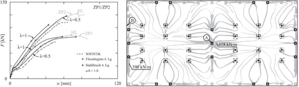
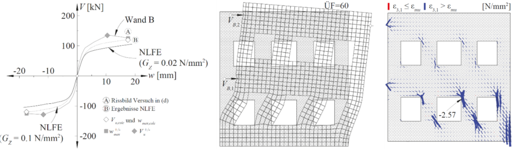
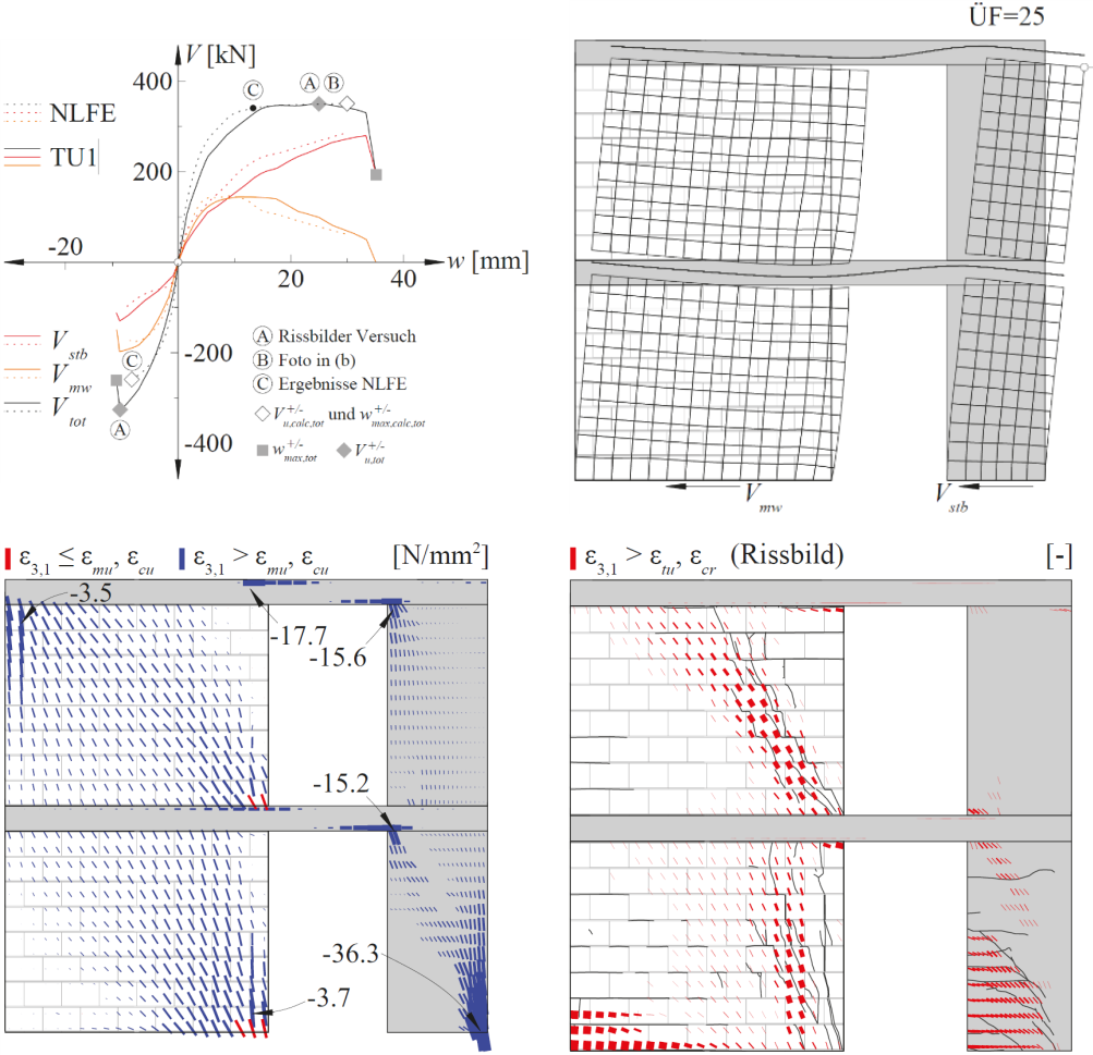
The URM-Usermat can be used to analyse the nonlinear load-bearing behaviour of unreinforced masonry structures (see Figure 5). The URM-Usermat is based on an implementation of extended failure criteria by Ganz (which were developed in the 1980s at the ETH Zurich and are still used today as the basis for masonry design) as user-defined material in the FEM program Ansys Mechanical APDL. In combination with the CMM-Usermat, the complex load-bearing behaviour of mixed structures made of reinforced concrete and masonry can be examined (see Figure 6).
All NLFE-tools have in common that the material models take into account the relevant properties of the load-bearing behaviour based on mechanically consistent relationships. In addition, only a few physically clearly defined input parameters are required, which are known in the design or assessment phase. This makes the NLFE-tools ideal for use in construction practice.
Future developments
The NLFE-tools are currently being implemented in the StrucEng Library, which is being developed at the Professorship for Concrete Structures and Bridge Design. The StrucEng Library is an open-source software that enables computer-aided calculations of load-bearing structures made of reinforced concrete and masonry. In addition to the nonlinear material models, various other material models are available, which cover the entire spectrum from structural design to analysis with linear-elastic ideal-plastic models. In the future, the StrucEng Library will be available in open-source format, which means that practical engineers can freely use the corresponding model using a user-friendly interface. In addition, the nonlinear material models are being further developed in various projects (e.g. corrosion, fibre-reinforced concrete, etc.). In the future, courses in the numerical modelling of reinforced concrete and masonry structures will also be offered at our Chair. With this special focus on numerical modelling in teaching and research, we are convinced that the prospective civil engineers will be fit for future challenges.
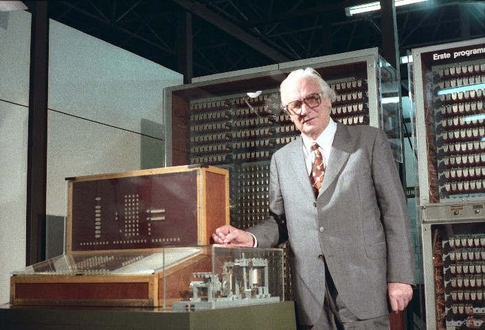
[1] Konrad Ernst Otto Zuse was a German civil engineer (!), inventor and entrepreneur. With his development of the Z3 in 1941, Zuse built the world's first working computer.
[2] In the context of these blog posts, nonlinearity always means material nonlinearity. There are also geometric nonlinearities (second-order calculations), which are taken into account via the P-Delta effect.
Marius Weber
Comment on this post on LinkedIn or Instagram