Link zu der deutschen Version: Entwicklung eines Materialmodelles für zyklisch beanspruchte Stahlbetontragwerke
At the Chair of Concrete Structures and Bridge Design, we have been using an in-house developed material model for the simulations of reinforced concrete (RC) structures for several years, among other things for simulations of existing SBB frame bridges. The simulations are so-called non-linear Finite Element (NLFE) analyses. The term “NLFE analyses” is described in the blog post “Finite Element Method in Civil Engineering“. As stated there, the basic principle of FE analyses in the field of structural engineering is to divide a complex load-bearing structure into many elements (discretisation) and mathematically link the elements to form an overall model. Besides the geometry of the structure, the loading and the boundary conditions/supports, FE analysis also requires a material model to link (at the element level, more precisely at the integration points) the forces or stresses to the deformations or strains. The non-linear material model used at our chair, called CMM-Usermat, accurately simulates the stiffnesses (= force / deformation or = stress / strain) of membrane, slab and shell elements. The structural deformations, failure modes and maximum loads observed in tests are generally well represented by the simulations based on this material model. For a more in-depth look at the structure and verification of the material model, I refer the reader to the following literature: [1]-[4]. The CMM-Usermat is currently limited to unidirectional loads, i.e. only monotonically increasing loads can be considered; unloading and reloading cannot yet be simulated.
As a logical next step in the development of the material model, it should be generalised so that unloading and reloading / cyclic loading can be applied. This allows us to perform simulations of the structures under cyclic loading (e.g. caused by earthquakes) in the time domain, a so-called time history analysis. The scope of my doctorate includes this further development of the RC material model. The research project aims to use the cyclic material model to carry out stable and reliable FE analyses that reproduce the load-bearing behaviour of RC structures subjected to cyclic loading as accurately as possible. Caminada has already addressed this topic during his master’s studies at the Lucerne University of Applied Sciences and Arts (HSLU) and obtained promising results [5]-[7], which justify more in-depth research.
Funding of the research project:
The research project described in this blog post is funded by the Swiss Federal Nuclear Safety Inspectorate (ENSI) and accompanied by its technical experts. The project is scheduled to run for three years and will end in 2025. ENSI promotes research in the field of seismic verification and analysis of RC structures relevant to its regulatory activities. Further information on ENSI’s research can be found in the annual research and experience report.
In the following, the structure of the cyclic material model is described, whereby CMM-Usermat-U and CMMUsermat-C denote the unidirectional and cyclic material model, respectively.
RC in a nutshell (for non-civil engineers):
Concrete is relatively strong in compression but an order of magnitude weaker and brittle in tension. The low and uncertain concrete tensile strength is thus commonly neglected at the ultimate limit state. Instead, the concrete is reinforced in at least two (usually orthogonal) directions with ductile steel bars, which have a very high tensile strength compared to concrete. This combination of concrete and reinforcement results in the characteristic structural behaviour of RC: tension is resisted by the reinforcing bars (after the concrete has cracked) and compression is predominantly carried by the concrete.
As highlighted by this brief description of its constituents and load-carrying behaviour, RC cannot be treated as a homogeneous isotropic material. In particular, the interaction of the reinforcing bars with the concrete is highly complex and its modelling requires certain simplifications.
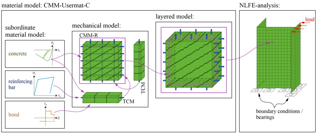
To obtain a good approximation for the complex RC load-bearing behaviour, the CMM-Usermat-C is structured into three levels: subordinate material models, mechanical models and the layered model (see Figure 1).
The subordinate material models describe the stress-strain relationships of the RC components (concrete and reinforcement) as well as the bond stress-slip relationship between concrete and reinforcement. A library of different subordinate material models for concrete, reinforcement and bond is currently being built.
The mechanical models, which form the core of the CMM-Usermat-C, abstract the load-bearing behaviour of RC elements in such a way that the essential mechanisms, including the interaction of the RC components, are represented. The focus is on mechanically consistent modelling in which both the equilibrium of forces and compatibility (strains and stresses comply with the described subordinate material models for reinforcement and concrete at every point in space and time) are fulfilled. The CMM-Usermat-C is based on the Tension Chord Model (TCM) [8], which takes into account the contribution of concrete between cracks (tension stiffening), and the Cracked Membrane Model with rotating, stress-free cracks (CMM-R) [9], which models the load-bearing behaviour of shear-loaded membrane elements. The TCM and the CMM-R access the library of subordinate material models for the material behaviour of the RC components. Side note: The name of the material model CMM-Usermat-C is derived from the mechanical model CMM-R, where “Usermat” stands for “user-defined material”.
The third and highest level in the CMM-Usermat-C represents the layered model [10], which is responsible for extending the mechanical models (1D and 2D) to three-dimensional slab or shell elements. Thereby, the slab or shell element is divided into layers, assuming an in-plane stress state for each layer. The individual layers can be simulated with the mechanical models described above. All resulting forces in the layers are added/integrated and result in the section forces (membrane forces, bending and twisting moment) at a certain point in the FE mesh.
After explaining the overall structure of the CMM-Usermat-C, the next two sections describe the specific extension of the TCM to cyclic loads and the verification of the TCM for cyclic loading based on simulations of a cyclically loaded tension chord test.
Extension of the TCM to cyclic loads
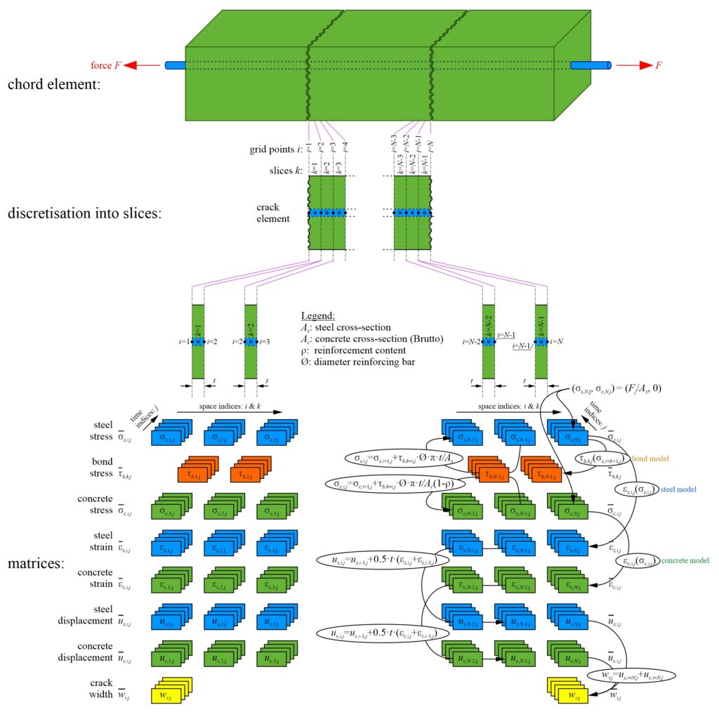
The TCM within the CMM-Usermat-C is used to simulate the relationship between average longitudinal strain and steel stress at a crack for a 1D RC element loaded in tension. An analytical solution for the relationship between average longitudinal strain and steel stress at a crack, as used for unidirectional loading (CMM-Usermat-U), is difficult to achieve for cyclic loading, given the infinite number of possible load histories. Therefore, an algorithmic solution was implemented in which the 1D tension chord is divided into finite slices. Stresses, strains and displacements in the reinforcement and concrete are calculated slice by slice (see Figure 2). It is assumed that the bond shear stress is constant across the thickness of the slices. All variables (σs, σc, εs, εc, us, uc, wr) except the bond shear stress (τb) are evaluated at the grid points between two adjacent slices. Based on the equilibrium of forces, the stresses in the reinforcement and the concrete and the bond shear stresses can be determined. With the subordinate material models, the calculated stresses in the reinforcement (σs,i) or concrete (σc,i) at grid point i can be related to the strains (εs,i, εc,i) and bond stresses (τb,k).
Verification of the TCM for cyclic loading
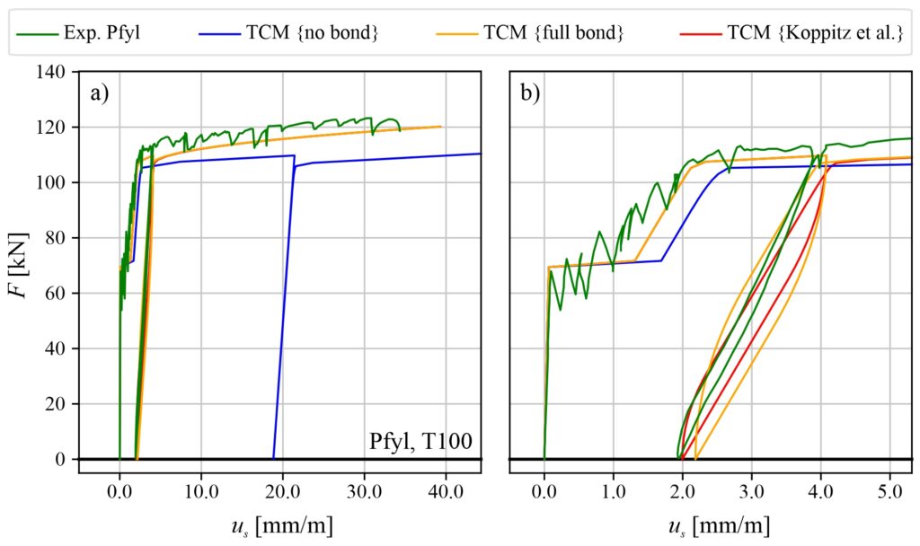
The cyclic TCM algorithm implemented in Python can be used to simulate tension tests on RC elements. The results of three simulations and one test carried out by Pfyl [11] are shown in Figure 3. The RC tension chord is loaded until cracks form. After a further load increase, the stress in the reinforcement exceeds the yield point. The load is then reduced to zero and increased again until failure is reached. Figure 3 shows that the TCM simulations reproduce the overall behaviour of the experiment well, although there are significant differences between the bond models {full bond; Koppitz et al [12]} and {no bond}. The latter does not consider tension stiffening in the cracked elastic phase and overestimates the deformations in the plastic phase. The TCM simulations with the bond models {full bond; Koppitz et al. [12]} overestimate the energy dissipation during unloading and reloading (hysteresis loop), whereas the bond model {Koppitz et al. [12]}, which considers bond damage after unloading, deviates less from the experimental curve than the bond model {full bond}. The results of the simulations are generally satisfactory.
Further descriptions and results will follow as the project progresses.
Simon Karrer
Literatur
[1] P. Roos, “FEM Modelle für Stahlbetonplatten – Verifizierung des Schichtenmodells anhand von Bauteilversuchen”, Hochschule Luzern Technik & Architektur, Horw, 2014.
[2] K. Thoma, P. Roos, and M. Weber, “Finite-Elemente-Analyse von Stahlbetonbauteilen im ebenen Spannungszustand”, Beton- und Stahlbetonbau, vol. 109, no. 4, pp. 275–283, 2014, doi: 10.1002/best.201300087.
[3] K. Thoma, P. Roos, and G. Borkowski, “Finite Elemente Analyse von Stahlbetonplatten”, Beton- und Stahlbetonbau, vol. 109, no. 12, pp. 895–904, 2014, doi:10.1002/best.201400047.
[4] K. Thoma, “Finite element analysis of experimentally tested RC and PC beams using the cracked membrane model”, Engineering Structures, vol. 167, no. 15, pp. 592–607, Jul. 2018.
[5] T. Caminada, “Zuggurtmodell – zykische Beanspruchug”, Vertiefungsmodul I, Fachgruppe Massivbau HSLU, Horw, 2017
[6] T. Caminada, “Normalkraft beanspruchte Betonelemente”, Vertiefungsmodul II, Fachgruppe Massivbau HSLU, Horw, 2017
[7] T. Caminada, “Gerissenes Scheibenmodell für zyklische Beanspruchungen”, Master’s Thesis, Fachgruppe Massivbau HSLU, Horw, 2018
[8] P. Marti, M. Alvarez, W. Kaufmann and V. Sigrist, “Tension Chord Model for Structural Concrete”, Structural Engineering International, vol. 8, no. 4, pp. 287–298, Nov. 1998, doi: 10.2749/101686698780488875.
[9] W. Kaufmann, “Strength and Deformations of Structural Concrete Subjected to In-Plane Shear and Normal Forces”, Doctoral dissertation, Institut für Baustatik und Konstruktion, ETH Zürich, Basel, 1998. doi: 10.1007/978-3-0348-7612-4.
[10] H. Seelhofer, Ebener Spannungszustand im Betonbau: Grundlagen und Anwendungen. Zürich: vdf Hochschulverl. an d. ETH, 2010.
[11] T. Pfyl and P. Marti, Versuche an stahlfaserverstärkten Stahlbetonelementen, vol. 268. 2001. [Online]. Available: https://doi.org/10.3929/ethz-a-004273447
[12] R. Koppitz, A. Kenel, and T. Keller, “Tension Chord Model Modification for Uniaxial Unloading and Reloading in Elastic and Plastic States”, Journal of Structural Engineering, vol. 140, no. 10, p. 04014077, Oct. 2014, doi: 10.1061/(ASCE)ST.1943-541X.0000999.