Link zu der deutschen Version: Traglastverhalten von Stahlbetontübbingfugen
It may be rather surprising that the chair of concrete structures and bridge design is also involved in tunnelling. However, precast concrete tunnel lining segments are frequently used in tunnels built with a tunnel boring machine (TBM) and due to the large number of segments required, optimising the lining segments can have a major impact on the tunnel construction project. Leaner tunnel linings could significantly reduce cost and environmental impact as a thinner lining would not only use less construction material but, more importantly, reduce the required excavation.
The segments take on a wide range of tasks: Absorb the rock pressure, seal the tunnel, serve as a fastening element for equipment, and transmit the drive and control forces of the tunnel boring machine. The corresponding forces must be considered in the design of the segments, for which the joints play a key role.
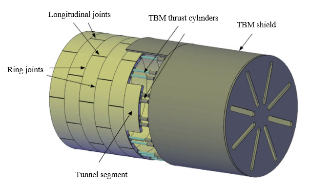
The longitudinal joints between segments (see Figure 1) transfer the loads during construction and the entire service life in one-pass lining systems. Large circumferential compressive forces typically occur in tunnels with significant overburden or squeezing grounds. The contact surface in the longitudinal joints is generally reduced compared to the full cross-section of the segments to ease installation, avoid spalling and place watertight gaskets. Due to the reduced contact surface, compressive stresses are higher at the load introduction area, and splitting tensile stresses occur further away due to the load dispersion. The lining thickness of tunnels with large circumferential compressive forces is often governed by the design of the longitudinal joints.
In shield-driven tunnels, the concentrated compressive loads of the TBM thrust cylinders distributed around the circumference act on the last installed segment ring and are transferred to the previously installed segment rings by the ring joints (see Figure 1). The tensile stresses resulting from load dispersion and assembly tolerances often govern the reinforcement design for crack width limitations.
An ongoing research project at the chair of concrete structures and bridge design, supported by ASTRA and BAV, investigates the longitudinal and ring joints of tunnel lining segments and aims to provide improved design approaches. This blog post focuses on the longitudinal joints and will present results from an experimental campaign.
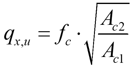
The structural behaviour of longitudinal tunnel lining joints can be represented as a partial area loading problem, with predominantly unidirectional load dispersion. It can thus be reasonably idealised as strip loading where a member is subjected to a line load, applied over a narrow width and extending over a much larger length, eventually spreading over the whole cross-section. Based on extensive test series, it is known that for partial area loading significantly higher contact pressures than the uniaxial concrete compressive strength can occur. Most current design approaches for partial area loading (e.g. SIA 262, Eurocode 2 and fib Model Code 2010) rely on the so-called square-root equation. It relates the average bearing capacity of the loaded area, expressed as stress qx,u, to the uniaxial compressive strength fc and the square root of the ratio of the area available for load dispersion Ac2 and the loaded area Ac1:
The square-root equation is purely empirical, consequently, standards restrict its use by several conditions: geometrical similarity of Ac1 and Ac2, limitation of the strength increase to a factor of three, and a requirement of transverse reinforcement to account for the bursting stresses. The first condition strongly limits the strength increase for longitudinal tunnel lining joints. The required resistance of the bursting reinforcement can be reliably determined from a simple strut-and-tie model. It is important to mention, that the square-root equation does not consider the beneficial effect of transverse reinforcement located in the vicinity of the load application area, nor that of bursting reinforcement exceeding the minimum amount required. Experiments revealed that longitudinal tunnel lining joints can sustain substantially higher loads than predicted by the square-root equation. However, conducting project-specific tests is expensive and time-intensive.
As an alternative to the square-root equation, longitudinal tunnel lining joints can be designed as structural members with confinement reinforcement, e.g. according to SIA 262, paragraph 4.2.1.8. This is a mechanically sound approach that is mainly used in the design of pre-stressing anchorages and short compression members. This approach enables the activation of transverse reinforcement – both close to the load application and where bursting reinforcement exceeds the minimum amount required for load dispersion. However, it neglects the beneficial influence of load dispersion in partial area loading. In addition, uncertainties exist to what extent the reinforcement can be activated and whether spalling of the cover concrete can already occur in the serviceability limit state. According to SIA 262, combining the square-root equation and the beneficial effect of confinement reinforcement is not allowed. Nevertheless, it is well known that load dispersion and reinforcement positively impact the bearing capacity of partially loaded areas.
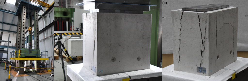
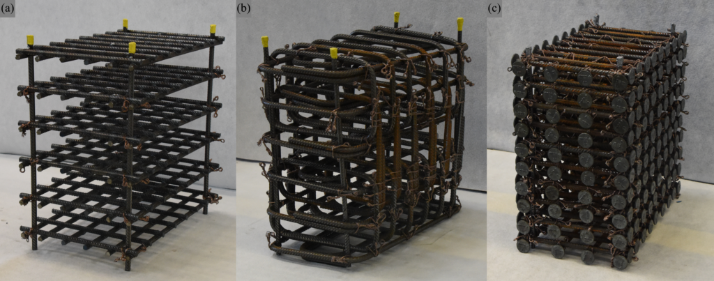
Only a few experiments have been carried out on specimens with significant confinement reinforcement subjected to strip loading in the past. Because of this an experimental campaign on 20 strip-loaded reinforced concrete blocks (350x550x525 mm3) was conducted. The samples were tested with a 20 MN Amsler compression testing machine at Empa in Dübendorf, Switzerland (see Figure 2). The specimens were either made of normal-strength concrete, high-strength concrete or fibre-reinforced concrete and were reinforced with welded grids, bent ties or double-headed bars continuously placed in the transverse and longitudinal direction over the full height (see Figure 3). The samples were loaded with small steel bricks over a continuous length of 450 mm and a width of 140 mm or 210 mm, corresponding to load concentration ratios of 40% (= 140 mm / 350 mm) and 60% (= 210 mm / 350 mm), respectively. All specimens but two were centrally loaded.
The following conclusions can be drawn from the experimental campaign:
- Increasing the reinforcement amount leads to higher bearing capacities.
- Geometric reinforcement contents up to 4% in the transverse direction can be activated.
- Welded grid reinforcement exhibits similar load-bearing behaviour as bent ties and double-headed bars.
- Samples with hybrid reinforcement (conventional reinforcement combined with steel fibres) sustain higher bearing capacities than samples with the same amount of only conventional reinforcement.
- The bearing capacity of strip loaded reinforced concrete blocks, normalised by the concrete strength, decreases with higher concrete strength.
- A smaller load concentration ratio results in a higher bearing capacity qx,u,exp. Note that despite the increase of the stress qx,u,expwith reduced loading width, the peak load decreases due to the smaller loaded area.
For further details regarding the experimental campaign, the reader is referred to Morger and Kaufmann.
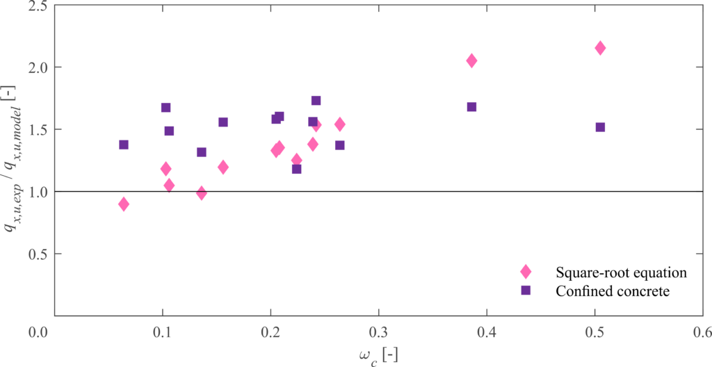
Figure 4 presents the ratios of the experimentally observed average bearing capacities qx,u,exp to those predicted by the different models qx,u,model plotted versus the mechanical reinforcement ratio ωc. Only centrally loaded specimens out of normal and high-strength concrete are shown in Figure 4. For the square-root equation, it can be seen that the reliability of predictions decreases with increasing reinforcement ratios. Note that the condition on geometric similarity was neglected. Otherwise, much more conservative predictions result. Considering confinement, the influence of different reinforcement ratios is captured, but this approach consistently underestimates the bearing capacity since the impact of load dispersion is neglected.
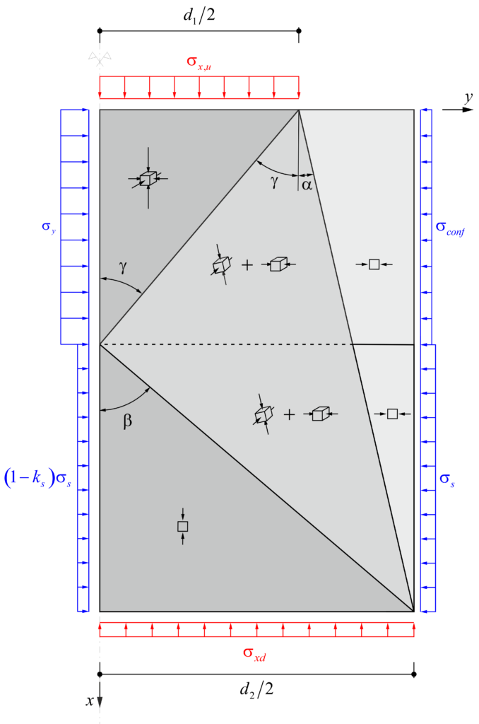
The recently published mechanically consistent Dual-Wedge stress field (see Figure 5 or Markic, Morger and Kaufmann) takes load dispersion and confinement reinforcement into account. In comparison with the square-root equation and the confinement approach, the Dual-Wedge stress field provides accurate predictions of the bearing capacity for strip-loaded reinforced concrete blocks. The detailed comparison of the dual-wedge stress field with the experiments will be presented in an upcoming publication.